Industrial Embedded Articles
LabVIEW hardware interfacing and integration
LabVIEW hardware interfacing and integration
With NI hardware or non-NI hardware
LabVIEW is a dominant development platform for all types of automated measurements and control. Developers of automated systems, such as test systems, need to interface with hardware. Examples range from basic digitizing of analog values to controlling a telescope. With the huge array of hardware options, you may be wondering if LabVIEW can interface to absolutely any type of hardware. This article reviews why LabVIEW is such a good development platform for hardware interfacing, based on our decades of using LabVIEW in a wide range of test systems.
In this article we’ll go over:
- Common use cases for interfacing / integrating LabVIEW with hardware
- Tips for interfacing / integrating with hardware
- Lessons learned / gotchas when interfacing / integrating with hardware
- Next steps if you’re looking for help
Common use cases – why do people interface LabVIEW with hardware?
There are two main reasons for using LabVIEW to interface with hardware.
- LabVIEW natively supports so many types of hardware from NI and is designed to support hardware made by other vendors. In fact, most vendors offer LabVIEW drivers with their hardware since LabVIEW is so commonly used.
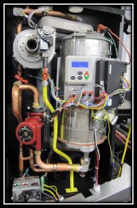
- Many systems (e.g., automated test, industrial embedded) need to interface with the real world by taking measurements, controlling actuators, or communicating with other hardware.
No single supplier of hardware for measurement and/or control can satisfy all needs. You may have:
- unique data acquisition sample rate needs,
- schedule or budget constraints that require effective implementation,
- uncommon measurement needs,
- or unique sensor types.
LabVIEW offers an open and flexible development platform to handle all these scenarios.

Tips for interfacing LabVIEW with hardware
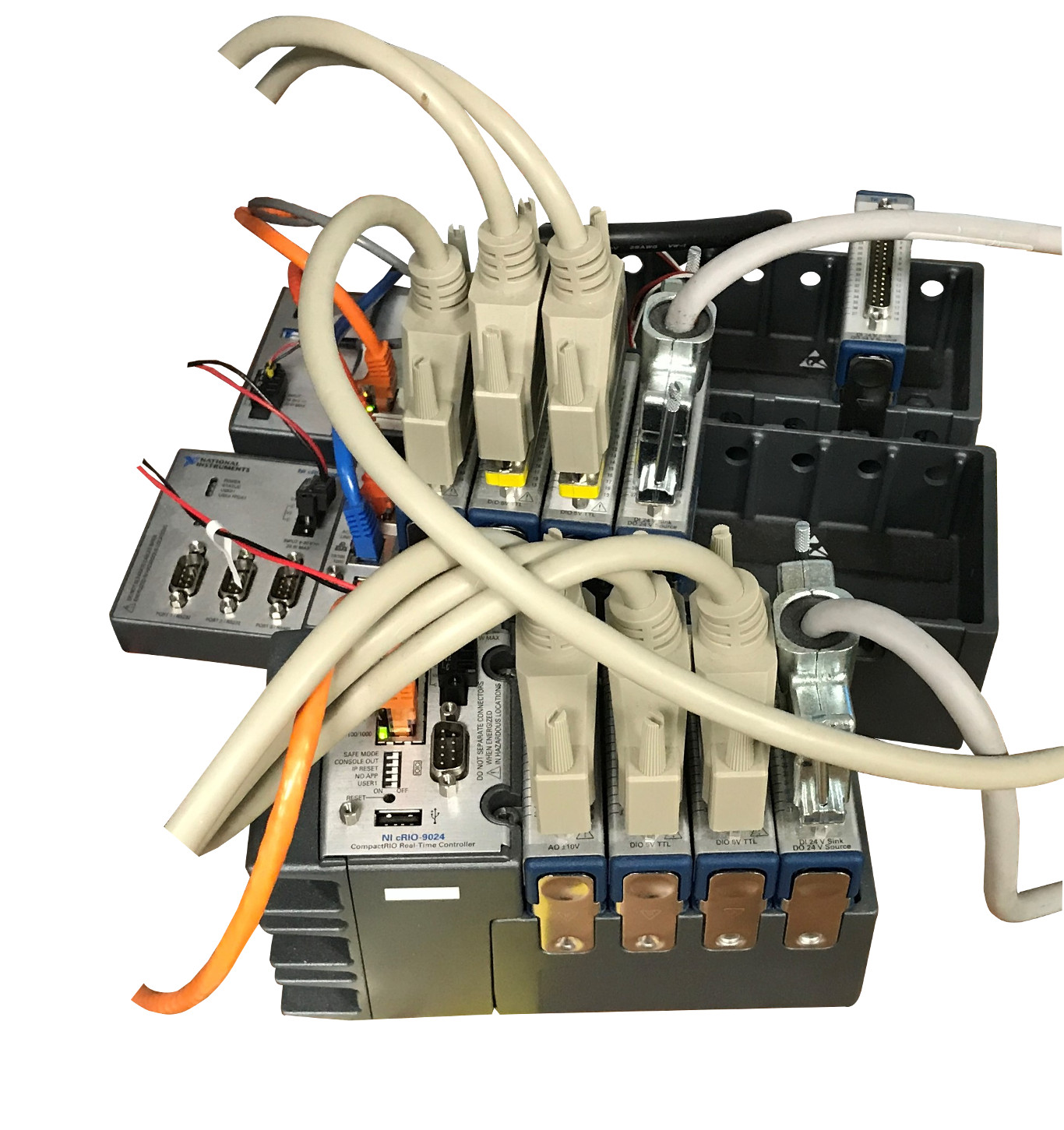
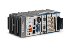
LabVIEW works natively with hardware offered by NI, mainly through the DAQmx drivers or, if you’re using NI’s CompactRIO hardware, through the additional methods of Scan Mode and FPGA nodes. This support is the primary reason that most LabVIEW developers choose NI hardware: it’s just easier to use.
The rest of this section discusses using LabVIEW with non-NI hardware.
LabVIEW drivers
The first step you should take will be to check if the hardware vendor has LabVIEW drivers for the instrument you need.
It’s rare to find a vendor that doesn’t have LabVIEW drivers.
If a driver is available, we recommend that you check that the driver supports the functionality you need in the application you’re developing.
For example, some drivers offered by vendors don’t work well if you have several of the same instrument in one system. Or the driver might be slower to respond than you’d like. In these cases, you might be able rework the example code offered by the vendor to make it do what you want, or you may have to write your own driver.
Hardware interface connection schemes
Review the connection scheme. Almost all instruments support an interface using messages sent over a communications protocol.
Common protocols (in no particular order) include:
- GPIB: a solid standard still in use, but being replaced with Ethernet
- RS-232 serial: a persistent standard even though it’s low-level and somewhat finicky to set up
- Ethernet: very capable, but connect such instruments only to your PC or controller to avoid IT concerns about hanging an unknown device off the corporate network
- USB: also capable and easy to setup, but may not be as reliable as Ethernet
Note that the VISA standard supports many of these protocols.
If the vendor doesn’t have a LabVIEW driver, you’ll need to learn the interface for the instrument for commands sent to, and responses sent by, the device. You may be surprised by the huge extent and intricacies of the entirety of the messages and their formatting needs. Drivers for some non-NI instruments are not at all trivial, e.g., the 160+ pages of commands for a Keysight signal analyzer.
Best methods to interface LabVIEW with instruments
The best method to consider when interfacing LabVIEW to instruments is VISA, which is a common abstracted bus interface for instruments. VISA supports many bus protocols such as GPIB, USB, and Ethernet communications.
If the instrument does not have a VISA driver for LabVIEW, you can still interface to the device using direct calls for whichever protocol the instrument supports. For example, if the instrument supports Ethernet, you’d open an Ethernet port and read/write messages to the IP address of the device.
Interfacing LabVIEW with custom hardware
The need to develop a driver for custom hardware is rare and specialized. The effort depends heavily on what the custom hardware does and how communication is handled.
There are 3 approaches worth considering:
- First, the custom hardware might be controlled and monitored via analog or digital signals, which would be handled by an appropriate NI card(s) via the DAQmx driver.
- The next level of complexity would be a device with communication to LabVIEW via RS-232, Ethernet, and so on. Then you could use LabVIEW’s tools (e.g., VISA) to talk with the device.
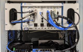
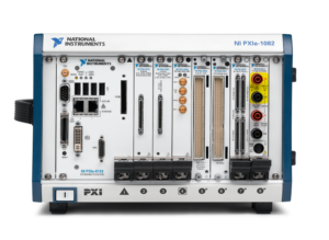
- Finally, a plug-in PXI card in a chassis with a Windows-based controller. This would require significant software development for the operating system (OS): first just to recognize the card so that the OS would recognize it, and then second, low-level drivers that follow the development needs of the driver model so that LabVIEW could talk to it.
Alternatives to LabVIEW for hardware interfacing
LabVIEW has a much more robust and developed set of tools and a development environment than other languages, especially for NI hardware.
However, both Python and C# (and by extension C and C++), and other languages too, have ways to interface with just about any type of hardware. For example, NI offers Python wrappers for DAQmx to support their hardware. For non-NI hardware, you may be able to find drivers or wrappers for your preferred development language or you would drop back to using low-level calls or communications protocols and building up your driver from scratch.
Lessons learned & gotchas to look out for when interfacing hardware with LabVIEW
At Viewpoint, we’ve interfaced to countless pieces of hardware over decades, most from NI, but many times from other vendors due to the wide range of test systems we’ve developed and delivered to customers with incredibly diverse measurement and control needs.
Some of the more impactful gotchas to keep in mind when interfacing LabVIEW with hardware are:
- Using the hardware in ways that are incompatible with the desired measurements or control.
- Using hardware outside of its specs.
- Underestimating the development time.
- Forgetting to save and restore the instrument configuration.
Some details regarding each of these:
Using the hardware in ways that are incompatible with the desired measurements or control
- Doing single point updates/reads when buffered I/O is needed to keep up with the desired rate.
- Incorrect configuration of synchronization across I/O channels.
- Acquiring/outputting more data than can be handled by the PC/controller.
- An example of a nitpicky but head-scratching detail is the mixing Delta Sigma (DS) and successive approximation (SA) A/Ds. Since DS converters delay their output relative to SA, skews in signal timing appear.
Using hardware outside of its specs
- Unattainable sample/update rates, whether too slow, fast or between allowable rates.
- Out of range or under range inputs can lead to acquired signals that are clipped, or so low in amplitude that only a few of the quantized bits are utilized.
- Out of range outputs can result in non-functioning actuation. Perhaps the more prevalent issue in this item is driving a digital output from the hardware into a unit under test (UUT) that expects more current than the hardware can provide. We’ve seen this issue with some of our customers trying to use an analog output to control a relay, but it can also happen with digital outputs. Also, too much current or too high a voltage can destroy the UUT.
Underestimating the development time
- If the driver exists: the time needed to learn and utilize the driver can be much more than initially expected; some vendor drivers are complicated.
- If the driver doesn’t exist: the time needed to learn the instrument‘s interface and develop a driver can be daunting.
Forgetting to save and restore the instrument configuration
- If the instrument resets after a power cycle, the configuration might return to factory setting, rather than what you expected to make your measurements for your test.
- If the instrument configuration is changed by another application or by pressing some manual buttons or menu items, the instrument needs to be returned to the configuration you expect before your test proceeds.
Next Steps
If you’re trying to select test hardware and feeling overwhelmed by NI’s massive catalog of hardware options, check out our NI Hardware Selection Services.
If you’re in learning mode, here’s some info that you might find useful:
- NI Hardware Compatibility – real-world tips and lessons learned
- What should I keep in mind when I’m launching a new product and considering a custom manufacturing test system?
- What should I keep in mind when I’m launching a new product and considering a custom product validation system?
- Using LabVIEW for automated testing
- Tips for improving manufacturing test with advanced test reports
- Tips for improving design validation with advanced test reports
- How to improve a manual testing process
- Hardware testing process – How to test products during production
- Design validation testing with LabVIEW
- Hardware test plan for complex or mission-critical products
- Product testing methods for industrial hardware products
- Which NI platform best fits my automated test needs? cRIO, PXI, cDAQ?
- Instrument Control with LabVIEW
- How to prepare for when your test team starts to retire
- Practical manufacturing test and assembly improvements with I4.0 digitalization
- What to do with your manufacturing test data after you collect it
- 5 Keys to Upgrading Obsolete Manufacturing Test Systems
- How Aerospace and Defense Manufacturers Can Make the Assembly and Test Process a Competitive Advantage
- 9 Considerations Before you Outsource your Custom Test Equipment Development
- Reduce Manufacturing Costs Report
- Improving Manufacturing Test Stations – Test Systems as Lean Manufacturing Enablers To Reduce Errors & Waste
LabVIEW Remote Monitoring

LabVIEW Remote Monitoring
6 ways to do remote monitoring with NI LabVIEW
In this article, we define LabVIEW remote monitoring as acquiring measurement data from a distant location (e.g., the other side of a factory, a different building, or halfway around the world) from where the data is to be analyzed/utilized. The data might simply be viewed before later use or it might be written to a database for further analytics.
So what might you want to remotely monitor and from where?
- Test equipment on the factory floor from your office
- Power generation equipment at some remote customer site halfway around the world
- A product out in the field back at corporate
Since this article was originally published in 2018, NI’s support for web-based application has exploded. Some of the original methods we originally discussed, such as LabVIEW Remote Panels, have been superseded, while others, such as LabVIEW Raw TCP functions, remain.
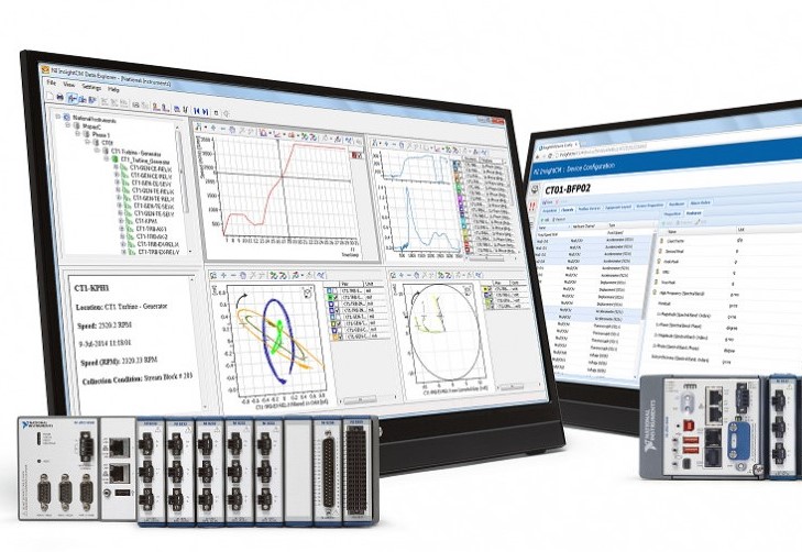
We’ve also removed NI InsightCM, since this platform has been transferred to Cutsforth and specialized to various specific monitoring applications.
While reviewing the methods below, keep in the back of your mind how you are going to manage the datasets your remote system will be sending you. So much work has been done to SQL databases and other supporting tools since we originally wrote this article that we strongly recommend you consider using a database to help organize and manage your data.
Here are the updated 6 methods for remote monitoring with LabVIEW:
- Windows remote desktop
- Raw TCP functions in LabVIEW
- LabVIEW network streams
- LabVIEW Web Server
- NI WebVI – G Web development
- NI SystemLink
Caution: there are lots of different options (with varying degrees of completeness) to use here. If you don’t know what you’re doing, you can end up with a non-working or at least a very error-prone application.
Windows remote desktop
What is it in a nutshell?
You can interact with a LabVIEW application that is running on a remote PC. You connect to that remote PC by using the Remote Desktop Protocol (now called Remote Desktop Connection) widely available since Windows XP.
What remote monitoring scenario is it best suited for?
If all you need to do is interact with an application and visualize graphs, remote desktop works well. However, control of this remote machine can only be done manually, just as if you were at the remote location sitting in front of the PC.
What should you know about it?
Transfer of data to another PC and control of the remote PC are manual processes. Also, the firewall configuration setup by IT may precent connecting to the remote PC.
Suggested LabVIEW Developer Level
Novice
Raw TCP functions in LabVIEW
What is it in a nutshell?
Yep, you can talk raw TCP in LabVIEW.
What remote monitoring scenario is it best suited for?
This method generally only makes sense when you want to create a custom messaging scheme on top of TCP, but with some of the other libraries available (like NI’s AMC), it’s best not to create your own unless it is required.
What should you know about it?
You’ll have a lot of control, but also a lot of opportunity to make mistakes.
Suggested LabVIEW Developer Level
Intermediate
LabVIEW Network streams
What is it in a nutshell?
A built-in method that provides a way to share data across a network. This capability is a step up from raw TCP and, while not as flexible, it is easier to use. A good overview about LabVIEW Network streams can be found on NI’s website. A very high-level explanation is also available.
What remote monitoring scenario is it best suited for?
Network streams do a good job of streaming lossless LabVIEW data from point to point over a network and is built using TCP and UDP.
What should you know about it?
This method is more accessible than raw TCP, but you’re going to have to write a lot of client/server processes. And, since this method is strongly focused on moving data, you might also perhaps want to consider having a web UI or the raw TCP functions to interact with the data sending application.
Suggested LabVIEW Developer Level
Intermediate
LabVIEW Web Server
What is it in a nutshell?
This service manages HTTP requests from LabVIEW VIs and other apps, such as written with HTML and JavaScript, to call LabVIEW VIs. The responses from those VIs need to be of a form that can be rendered by a browser or any other app that can consume the data served up by those requests.
What remote monitoring scenario is it best suited for?
Any time you wish to have a thin client on a remote PC, such as a browser, and wish to have LabVIEW VIs compose the responses.
Compared with LabVIEW WebVIs, discussed next, using the LabVIEW Web Server may be a simpler deployment and offer more flexibility, since you are closer to the raw HTTP messaging, but you have to do more development work to get to the same features that the WebVIs offer.
What should you know about it?
You’ll need to know about HTML, JavaScript, C#, and likely some of the many pre-developed libraries to build the code that creates the HTTP requests (e.g., GET method) and handles the responses.
If this approach sounds interesting, spend some 30 minutes with this overview video to learn more. Alternatively, consider working with a knowledgeable web developer to provide the web coding side of your project. With that path, this web work can be done in parallel with the LabVIEW coding and, if you’re not familiar with the web tool chain, you won’t have to educate yourself.
Suggested LabVIEW Developer Level
Advanced
LabVIEW WebVI – G Web development
What is it in a nutshell?
The G Web development application offers web development with familiar LabVIEW-like coding. At a basic level, the application builds the HTTP and JavaScript code that you’d have to write using the LabVIEW Web Server approach.
What remote monitoring scenario is it best suited for?
This approach is best applied to complicated monitoring applications or situations where you need to develop multiple web apps.
The WebVIs can interface with the LabVIEW Web Server. They also interface well with NI SystemLink, which is designed for monitoring the operational status of many machines. See below for an overview of SystemLink.
What should you know about it?
LabVIEW WebVI, also known as G Web Development on NI’s web pages, is an outgrowth of LabVIEW NXG. On some of NI’s webpages about WebVI, you may still see references to NXG, but NXG stopped being developed past 2022.
This development environment is only LabVIEW-like, and the dissimilarities with LabVIEW will require you to learn a new environment. Balance that fact against the knowledge ramp you’ll have to climb using the more basic Web Server approach.
An overview page of WebVIs on NI’s website holds additional details. And, NI has provided several examples such as using the NI Web Server and SystemLink Cloud, calling 3rd-party services like USGS data and JavaScript, and an application that uses multiple top-level VIs.
A recommendation would be to learn to do LabVIEW WebVI dev if you intend to make several web apps, since you’ll become faster at development with each additional app. You might also consider combining WebVI development with the web development environment embraced by professional web developers, which use HTML, JavaScript, C#, and so on. By combining your efforts with those of a professional web developer, you could focus on what you are good at and leave the web side to what they are good at.
Suggested LabVIEW Developer Level
Intermediate and Advanced
NI SystemLink
NI SystemLink is a platform for managing distributed systems in test and measurement. The platform is designed to remotely monitor variables from various PCs using the SystemLink UI. We’ve not familiarized ourselves extensively with SystemLink, but it may be worth looking into for applications that need to manage multiple data acquisition devices, querying and displaying device operational status, retrieving the status of the machine to which the device is connected, and transferring data to a central data store. And, it works tightly with the LabVIEW WebVI technology, so using both together may be the approach you are seeking.
What is it in a nutshell?
SystemLink is a piece of software developed by NI. Learn more from NI here: What is SystemLink? – National Instruments.
What remote monitoring scenario is it best suited for?
SystemLink is intended for use on test and embedded applications running on NI hardware for the purpose of publishing status and operational data for remote users. SystemLink can be deployed on-premise or in the cloud.
Coupled with LabVIEW WebVIs, complex remote visualization, control, and data management is available.
What should you know about it?
SystemLink is a complex platform, the learning curve is steep. Since this article is about remote monitoring, an important aspect of SystemLink is its ability to interface with LabVIEW WebVIs (a.k.a. G Web Development) for the purpose of developing UIs for interfacing to the remote PCs.
Some interesting links to learn more are:
- SystemLink Cloud Overview – National Instruments
- How Do I Create Custom Dashboards and Remote Operator Interfaces with the SystemLink Software Configuration Module? – National Instruments
- Calling SystemLink Data Services
Suggested LabVIEW Developer Level
Intermediate, Advanced, and Expert depending on the complexity of the application
Hardware required
Of course you’ll need to connect to or create a network of some sort (or at least a point-to-point link). Here’s some hardware that could be used to help you get connected remotely:
- Ethernet port & network
- Wi-Fi enabled device (e.g. http://www.ni.com/en-us/shop/select/c-series-wireless-gateway-module)
- Cellular enabled device (e.g., https://shop.sea-gmbh.com/SEA-9745-4G-Mobilfunk-Kommunikationsmodul-Kit/60000070-SEA-9745-Kit). You may need to contact your cellular provider to enable this device to connect to the cell network.
- Proprietary wireless communication systems for long range or high-speed communications (e.g., https://www.gegridsolutions.com/Communications/licensedSolutions.htm )
Next Steps
Once the remote, likely web-enabled, LabVIEW application is running, you will eventually want to consider the steps associated with handling all the remote data you will be accumulating. An approach that had proven itself over many decades is to use a database. The database empowers you with searching, sorting, and filtering capabilities to help you find, review, and process the selected data.
Not all raw datasets, such as large waveforms, need to reside in the database. In fact, it probably shouldn’t for reasons of database size and responsiveness. Regardless, we recommend storing at least enough baseline information to give you the means of locating all the large datasets not stored in the database that meet the query criteria.
Database design and interfacing is another whole topic not covered here. Many web developers also have skills in databases.
To learn more about LabVIEW-based remote monitoring with or without a web interface, check out these case studies:
- Industrial Equipment Remote Online Condition Monitoring
- Condition Monitoring – Improving the Uptime of Industrial Equipment
- Condition Monitoring for Electric Power Generation
- Remotely Monitoring Electrical Power Signals with a Single-Board RIO
- Industrial Embedded – Industrial Equipment Control
- Industrial Embedded Monitoring – Remote Structural Health Monitoring using a cRIO
- Online Monitoring of Industrial Equipment using NI CompactRIO
How to get help
If you work for a US-based manufacturer, looking for help with LabVIEW-based remote monitoring and possibly data management, you can reach out here.
6 Questions to Ask before you Buy a Standalone Data Acquisition System
Standalone Data Acquisition Systems
6 Questions to Ask yourself before you Buy
Do you need a standalone data acquisition system (DAQ) to measure a bunch of analog and digital signals? Here’s 6 things to think about before you pick one.
How long does it need to run for without interruption?
Days? Weeks? Months? Years? The duration you need will impact your choice of hardware & operating system more than anything else. If the processor is stressed keeping up with tasks, then there is a larger chance that data flow will get backed up and errors will occur from a buffer overflow. Spinning hard drives have moving parts and will wear out. Even the internal system time battery will cease to function after a decade or so (maybe sooner).
When it crashes, do you need it to auto-restart, call the mothership, or is there no serious need to recover from a crash?
Will it have access to a power source, or does it need its own power source?
If the standalone DAQ has access to prime power, that’s obviously a much easier scenario than having to supply your own portable power, like from a battery, solar panels, or some combination of various sources. Power and energy utilization calculations can get tricky for multi-mode operation or any scenario where the power draw varies significantly. Be conservative, take power measurements under real-world operating conditions, and consider temperature and cycle de-ratings for battery-based applications.
Does the DAQ need to be able to transmit data remotely from the field or a plant, or is local storage sufficient?
If you’ve got access to a fiber link or copper Ethernet, great. If not, this challenge can be often be met if:
- There’s access to a cellular tower or Wi-Fi network (there are other public and private radio alternatives as well if needed).
- EMI (Electromagnetic Interference) levels are below required thresholds for the link. If you really care if your link works, an RF site survey is warranted.
- The DAQ bandwidth needs are less than what’s available from the link.
Something to think about if you do have this need is whether the DAQ system needs store-and-forward capabilities to buffer acquired data when the link goes down and continue sending once the link is back online. And, how much storage would you need? You should consider a lower rate data stream, such as Modbus TCP, to uplink features computed from the raw data, so you at least have a view on status even if transmission bandwidth is low.
If local storage is sufficient, you’ll still want to think about what happens when the memory gets corrupted, loses sectors, or dies completely. How much data are you going to lose, and do you need to mitigate with redundancy techniques like memory mirroring. See our article on LabVIEW remote monitoring for more info.
Do you need to be able to access the data acquisition system remotely to configure it or check on its status?
Maybe you need to be able to modify one of the pre-trigger acquisition parameters, or maybe you find that you need to bump up the data acquisition rate, but your DAQ system is either in an inconvenient-to-access location in the plant, or maybe it’s half way around the world.
Or maybe you know some important event is happening in the next hour, and you want to view the status to make sure the DAQ is operational.
There are several ways to enable remote access to your DAQ. Depending on your specific needs and the hardware you select, you may be able to utilize built-in software utilities, or you may need custom software developed. See our article on LabVIEW remote monitoring for more info.
Do you need to simply acquire raw data, or do you need that data to be processed in some way post-acquisition?
Maybe you just need raw digital data to analyze on your PC after it’s acquired. But you may run into bandwidth or storage space issues if you keep everything you acquire, or maybe that extra data will just increase your processing/analysis time more than you can tolerate.
You may want to do some filtering, windowing, or maybe even some time- or frequency-domain processing before you record the data you’ve acquired. Depending on the amount of number crunching you need to do, a basic CPU may do the trick, or you may need a dedicated number crunching processor like a DSP, a multicore processor, or an FPGA.
What does your input channel list look like?
The biggest driving factors here will be related to:
- Sample rates – if your data changes very slowly and you only need to acquire data at a few samples per second, that’s a very different animal than collecting at hundreds of kS/s or even MS/s.
- # of signals/channels to acquire data from – are you just trying to measure a few TTL levels or 0-10V analog input voltages, or are you trying to measure temperature, vibration, force, pressure, etc. on dozens or hundreds of channels?
- Min/max/range of signals – this is where signal conditioning really comes into play. If you need to measure µA or mV, you’d better understand how to appropriately amplify, filter, and isolate that signal before it becomes a digital value.
- Synchronization – do some or all of your channels need to be digitizing measurements at the same time or can you tolerate some lag between samples across channels?
Do you like examples? Here are some case studies of standalone data acquisition systems we’ve developed:


If you’d like to chat about your standalone data acquisition system needs, you can reach out to us here.
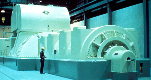
Continuous Monitoring & Data Acquisition from Large Industrial Equipment
Continuous Monitoring & Data Acquisition from Large Industrial Equipment
Why do it. How to do it. Gotchas. How to get help.
What are we talking about here?
We’re essentially talking about:
- Mounting some data acquisition hardware on a piece of industrial equipment and connecting various sensors to take measurements (e.g., temperature, pressure, current, voltage, vibration) from the equipment.
- Processing and sending the acquired data from the data acquisition hardware to some other location either in the building or half way around the world.
- Analyzing the data (either by hand or automatically) to make better decisions about the industrial equipment.
What better way to illustrate what we’re talking about then by showing a few case studies.
Why do it?
Generally, you’ll be interested in monitoring large industrial equipment because you want to better understand and track the health or condition of the industrial equipment, in order to spot trends in operating parameters that indicates reduced performance or even imminent damage.
How to do it
At a high level, you’re generally going to need to figure the following out:
- Make sure you have a business case for doing this monitoring, whether qualitative (e.g., customer satisfaction, ISO 50001) or quantitative (e.g., uptime, maintenance, lost production revenue).
- Determine what properties (e.g., vibration, temperature, current) make sense to monitor from your industrial equipment.
- Select the algorithms needed to compute features or trend those features. This may require proper data to be collected, depending on the sophistication of the algorithms.
- Select appropriate sensors and acquisition hardware to collect data at the required rates, range, sensitivity, and synchronization.
- Develop custom software or install a COTS application to process the data and send it off for analysis.
- Install and test the online monitoring system.
- Start collecting data for analysis at a small scale, show success, and iterate.
Gotchas to watch out for
- Remotely debugging is challenging. Be sure to include various event & error logging functions.
- Remote re-start when the monitoring system goes down.
- Remote reconfiguration of channels, acquisition parameters, and analysis.
- Not capturing enough training data to be able to massage the algorithms in order to give you the confidence that the monitoring system can detect fault conditions.
- Voiding the warranty on the industrial equipment.
- Safety concerns – do you have appropriate controls and safeguards in place?
- Cybersecurity – what is the monitoring system connected to, and what vulnerabilities did you just open up?
Depending on the amount of data being collected, you may also want to consider how you will assess any anomalous situations. If you are already performing route-based data collection, then your existing assessment processes will be adequate if you continue to collect data at the same volume. More likely you will collect more data, because it’s easy and incremental costs are insignificant, leading to a situation where you will either need to add staff to assess the extra data or you will have to automate the assessment process to help prioritize issues. If you’d like help creating an online monitoring system for your industrial equipment, reach out for a consultation.
LabVIEW Data Acquisition

LabVIEW Data Acquisition
Gotchas, tips & tricks, and how to get help
What is it and how’s it used?
LabVIEW-based data acquisition involves writing software on top of appropriate hardware to acquire data from various sensors (e.g., temperature, pressure, current, …). Those data are then usually manipulated and/or filtered before being displayed and/or recorded for further analysis.
LabVIEW is a software development environment created by National Instruments. Originally it was focused on taking measurements from various lab instruments, but it’s expanded drastically from its inception. Strictly speaking, LabVIEW is not a coding language, it’s a development environment. The language is actually called “G”, but most people refer to LabVIEW as if it’s a language (i.e., most people would say “it’s coded in LabVIEW”).
If you’re curious what sorts of acquisition LabVIEW is used for, check out this resource, which covers the 4 main uses for LabVIEW.
Gotchas:
Assuming that just because it’s easy to get started it’s also easy to finish. LabVIEW is a very complex programming environment. The good news is that there’s not much you can’t do with it. The bad news is that you have the freedom to get yourself into a lot of trouble (e.g., having sluggish user interfaces, dropped communication packets, acquisition buffer overruns, files that grow too large, creating control loops that won’t make timing, or have too much cycle-to-cycle variation).
Not organizing your LabVIEW code. Trust me, you won’t want a gigantic rats nest to try to debug, make updates to, or pass off to someone else in the future. With all those wires, LabVIEW brings graphical meaning to spaghetti code!
Hooking up a strain gauge or low voltage source (such as a thermocouple) sensor without signal conditioning. There are others. Signal conditioning is hugely important to be able to recover your signal(s) of interest.
Coding without requirements. It’s obviously more fun to just start banging out some code, but you’ll probably regret not taking a step back to at least jot down a bulleted list in a doc. Why? Because:
- You’ll want to know what you’re going to test in order to prove to yourself the thing works.
- It makes it more apparent if you’ve got conflicting requirements.
- It’ll help you think of other features you wanted but forgot about at one point or another.
If you’d like to start considering your requirements but aren’t sure where to start, feel free to check out our requirements templates (these might be more involved than is appropriate for your needs, but it gives you a starting point):
- industrial embedded requirements and specification template.
- test system requirements and specification template.
Assuming all downloadable instrument drivers will just work out of the box. Some instrument drivers are of great quality, while others are horrible. You’ll want to know where your driver falls on the spectrum, but for sure don’t assume it’ll just work. Get a sense of driver quality from feedback on various forums.
Assuming your application will just work the first time out of the box. It likely won’t. Make your life less stressful and allocate debugging time up front. As a very loose data point, consider allocating anywhere from 50%-150% of the time you spent coding on debug, depending on the overall complexity of course.
Not understanding what an FPGA is and how it works. You won’t always need an FPGA-based acquisition system, but if you do, you should understand that you’re coding a very different piece of hardware. If you’re looking to understand some of the very basics, see here: FPGA Basics – A Look Under the Hood.
Fundamentals – How to do it:
NI covers the basics well. See http://www.ni.com/white-paper/3536/en/. Also, check out this quick video from University of Minnesota: https://www.youtube.com/watch?v=GBhJk5Tnshc.
Tips & Tricks:
There are lots of ways to move data between loops in LabVIEW and to send commands along with the data to tell the receiver what to do with those data. Here are two methods, one tried-and-true and one which I bet you didn’t know: Communicating between Parallel Loops.
Another popular method leverages TCP/IP for communicating between sections of a single application or between multiple applications, either on the same PC or between PCs. Check out: Are You Using Network Streams?
Don’t find yourself knee-deep in a project only to find that you’ve got a sea of intermingled code, making it hard to differentiate what goes where and how to find files. Learn how to avoid this: Why Poor LabVIEW Project Organization Makes Your Code Stink.
If you want to do synchronous data acquisition across multiple channels, even if across boards, and perhaps even synchronized with output channels, you should check out: http://www.ni.com/product-documentation/4322/en/
LabVIEW uses data flow to sequence code execution. This approach offers inherent multitasking capabilities, including parallel tasks managed in multiple while loops. However, a desire arises to communicate between parallel tasks. Learn about several types of LabVIEW synchronization tools: Synchronization in LabVIEW.
How to get help:
If you’re looking for LabVIEW data acquisition help for your application, see here for how we can help solve your data acquisition problems.
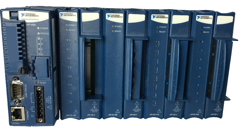
Migrating NI Compact FieldPoint to cDAQ or cRIO
Migrating NI Compact FieldPoint to cDAQ or cRIO
March 2018
Are you currently using a Compact FieldPoint (cFP) device and want to know what you should be thinking about to transition to a CompactRIO or CompactDAQ platform?
Are you doing control inside the cFP?
Are you doing any control with your system? If so, is it being done within the cFP, or is it actually being done on a PC connected to the cFP?
If you have control algorithms running at higher than 100 Hz, you’ll probably want to use a cRIO (or at least a cDAQ with an RT controller). The FPGA & real-time processor lend themselves well to high-rate deterministic loops, with the FPGA being able to run faster than RT.
Also, if you’re doing anything even remotely safety-related, you’ll want a cRIO, and sometimes you’ll even want to utilize a PLC or the FPGA side of the cRIO.
What can you do with the cFP that you can’t do with cDAQ?
I/O:
In general, beware of the size of the screw terminals available with cDAQ C Series modules; they tend to be smaller than are available with cFP modules. This smaller size can be an issue if your field wiring gauge is too big (i.e., smaller wire gauge number). Note that some C Series modules come in a couple connector styles that have built-in terminal blocks versus DSUB style connectors, the latter allowing cabling to larger terminal blocks with bigger screws.
Since there are many more types of C Series modules than cFP modules, you will almost certainly find a C Series module to replace your cFP module, but channel counts per module can be different (e.g., current output) and you might have to substitute a couple of C Series modules to accommodate all the I/O in a single cFP module (e.g., combined current input and output). The specifics of which C Series modules can replace the cFP modules are listed in the section below titled “Module limitations”.
Finally, note that, from an I/O module standpoint, many, but certainly not all, of the C Series modules are compatible with cDAQ (see here http://www.ni.com/product-documentation/8136/en/ for more).
Performance:
Being an older vintage, cFP is pretty limited from a CPU speed and memory capacity standpoint compared to a cDAQ with controller. Plus, the analog I/O in C Series typically has more bits than a comparable cFP module.
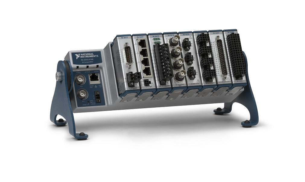
Using Controller or Just the I/O:
Originally, cDAQ chassis were used only for I/O and the “controller” was the PC you connected to the cDAQ chassis. Back around 2015, NI introduced a standalone cDAQ with a controller attached to a chassis for holding the I/O modules. If your cFP hardware is being used just for I/O and you are using a PC as the “controller”, you can continue with that same system design by using a traditional cDAQ module-only chassis. If you were using LabVIEW RT to run an application on the cFP controller, you can use a cDAQ controller system.
Software Application:
Whichever style of cDAQ you choose, you will have to rewrite some part of your application. Unfortunately, you can’t just move the cFP app onto cDAQ and expect it to work. The largest change will likely be in the I/O channel addressing, since cFP uses a completely different scheme for channel definition than DAQmx. But, since cFP applications followed a “single point” access scheme (rather than waveforms), the translation will be fairly straightforward, even if not trivial.
Environmental:
The cFP hardware has the same operational temperature range -40° to 70° C. the cFP has slightly better shock & vibration specs than the cDAQ hardware (50 g versus 30 g for shock, and 5 g vibration for both).
What can you do with cFP that you can’t do with cRIO?
Much of the remarks about moving to cDAQ from cFP also apply to moving to cRIO from cFP. However, some differences are listed below.
I/O:
The transition to C Series from cFP modules is the same for cRIO as cDAQ. Certainly, there are some C Series modules that don’t work with cDAQ and others that don’t work with cRIO, but none of these modules have comparable modules in cFP.
A point of difference is that using an FPGA to manage I/O via direct calls to the I/O channels, rather than going through FPGA Scan Engine (cRIO) or DAQmx (cDAQ) allows your cRIO much faster reaction. If your old cFP application depends on the slower responsiveness of the cFP controller and I/O, you may find that the cRIO system shows different behavior.
Performance:
The big change here, as alluded to earlier, is the availability of the FPGA in the cRIO. The cFP has nothing close to the performance capabilities available with an FPGA.
Software Application:
If your cFP application uses the cFP controller for the realtime capabilities, then a cRIO controller will give you all the capabilities you need to translate your application. As with cDAQ, the largest change will likely be in the I/O channel addressing, since cFP uses a completely different scheme for channel definition than Scan Engine or FPGA I/O. If you use the FPGA, while the I/O is programmed as single point access, you will still need to get those I/O values from your RT application layer into the FPGA, so there is another step involved. You’ll likely need to use a DMA FIFO.
Environmental:
The cRIO equipment can have the same operational temperature range as cFP of -40° to 70° C, but you can also purchase a cRIO controller with a smaller range of -20° to 55° C, so look for the extended temperature controllers if you need that wider range. Also, the cFP seems to have a slightly better shock & vibration specs than the cRIO hardware (50 g versus 30 g for shock, and 5 g vibration for both), but the cRIO controllers are tested to 30 g with a 11 ms half sine and 50 g with a 3 ms half sine over 18 shocks at 6 orientations. If it exists, it’s not easy to find from the NI literature exactly how the cFP equipment is tested for shock and vibration.
C Series Module Limitations
For the most part, whatever you could accomplish with a cFP from an I/O module standpoint, you can accomplish in a similar manner with a cRIO, with some notable limitations. See this NI white paper for more info: https://www.ni.com/en-us/support/documentation/supplemental/14/transitioning-from-compact-fieldpoint-to-compactrio.html.
Something to keep in mind as well is that there are 3rd party cRIO module manufacturers that may have what you’re looking for. See here: http://www.ni.com/product-documentation/2726/en/.
How to get help with a transition?
If you’d like help making the transition, Viewpoint can help. We used to use cFP back in the day, and we’ve used cDAQ & cRIO quite a bit. We’ve completed over 500 cRIO-based projects (see here for more). We’re also an NI Integration Partner.
Of course, there are tons of nuanced gotchas based on the specific cRIO/cDAQ model chosen, as well as your specific I/O needs. We can help you select modules and port code over to the new platform. To get started, it’s helpful to share whatever info you have revolving around: a hardware list, application overview, and source code. Feel free to reach out here to initiate a conversation.
Deep in learning mode? You might be interested in these resources:
- Online Monitoring of Industrial Equipment / Machines / Systems
- Which NI Platform is Right for Your Automated Test Needs? cRIO, PXI, cDAQ, sbRIO?
- NI Hardware Compatibility – real-world tips and lessons learned
- 6 Questions to Ask before you Buy a Standalone Data Acquisition System
- Continuous Monitoring & Data Acquisition from Large Industrial Equipment
- How to Diagnose Failing Custom Test Equipment
Why use LabVIEW
Why use LabVIEW?
There’s 5 main reasons to consider using LabVIEW:
- If you’re not a software developer but need to make quick measurements using real instruments – this requires little programming experience. However, to be clear, coding with LabVIEW requires you to follow good programming practices just like any other programming language. Like with any other programming language, garbage in equals garbage out.
- If you need tight integration between software and measurement/control hardware. LabVIEW has two targets that allow synchronization between measured inputs and calculated outputs. The first has on the order of 1 ms jitter and uses LabVIEW RT. The second has jitter on the order of 1 ns jitter and uses LabVIEW FPGA.
- Because your company is already heavily invested in the ecosystem – I know this sounds sort of like a “if Billy jumped off a bridge” analogy, but it’s not. While this isn’t my favorite reason to use LabVIEW, pragmatically, LabVIEW is a tool, and if your company is already heavily using this toolset, then you may be doing more harm than good by creating a separate parallel toolset to have to work with. Now you need to maintain multiple environments and maintain the expertise in two toolsets.
- It’s well-supported within the test & measurement community – from toolkits, to instrument drivers, to consultants that can step in if your main LabVIEW guy unexpectedly decides to leave your company.
- The development environment is user friendly.
- National Instruments works hard to make the LabVIEW development environment consistent across hardware platforms, from PCs running Windows to embedded controllers running a real-time Linux OS with connections to FPGAs for tight synchronization I/O. Most differences are included to take advantage of the resources of the specific platform so that the learning curve between platforms is about as small as it can get.
- The data flow paradigm inherent in LabVIEW makes coding parallel operations trivial.
- Each VI, which would be called a function in most other languages, comes with a user interface and a code block. Since you create a user interface for each function, debugging is much more visual than using user-defined breakpoints and probes.
- LabVIEW’s brings together all the code, hardware, and build definitions into one location under the Project Window.
Another closely related question that you might want an answer to is “What is LabVIEW used for?”. This article explains the main applications that LabVIEW is used for, with case studies, how LabVIEW interacts with the real world, and what hardware LabVIEW runs on. If you need LabVIEW help and want to know what your options are, check out this article on LabVIEW Help – What are my options?.

What is LabVIEW used for?
What is LabVIEW used for?
LabVIEW is used for 4 main purposes:
- Automated Manufacturing test of a component/sub-system/system.
- Automated Product design validation of a component/sub-system/system.
- Control and/or monitoring of a machine/piece of industrial equipment/process.
- Condition monitoring of a machine/piece of industrial equipment.
(If you need LabVIEW help and want to know what your options are, check out LabVIEW Help – What are my options?. If you’re looking for why you might consider using LabVIEW, see our article Why use LabVIEW. If you’re just looking for some basics about what LabVIEW is, see What is LabVIEW?)
There are likely some additional corner cases out there, but this covers the vast majority of applications we see at Viewpoint. Historically, LabVIEW has been widely adopted in the automated test realm, essentially becoming the de facto standard in that application space, whereas more recently it’s been gaining traction within the realm of industrial embedded monitoring and control.
LabVIEW is a software development environment created by National Instruments. Originally it was focused on taking measurements from various lab instruments, but it’s expanded drastically from its inception. Strictly speaking, LabVIEW is not a coding language, it’s a development environment. The language is actually called “G”, but most people refer to LabVIEW as if it’s a language (i.e., most people would say “it’s coded in LabVIEW”).
LabVIEW is graphically-based, meaning you drag around various building blocks and connect them in a data flow architecture. It’s similar to drawing a block diagram, except you’re drawing your code, as opposed to text-based languages like C# & VHDL where you type out in text what you want the software to do.
Poll – Test engineering leaders: What would help you most? Vote and see how your peers voted!
What basic functions can LabVIEW perform?
LabVIEW can be used to perform a huge number of mathematical and logic functions, including, but certainly not limited to: basic arithmetic, if/then/elseif conditional statements, case statements, FFTs, filtering, PID control loops, etc. There are huge libraries of functions to pull from. You can also interface to code developed in other languages, through DLLs. .NET assemblies, and run-time interpreters (e.g., MATLAB), for example.
Another somewhat unique capability that LabVIEW offers is real-time compilation and the ability to execute function blocks without requiring development of a test case. Each LabVIEW function is designed with a user interface so you can interact with your code immediately after you write it.
LabVIEW use case – Automated Manufacturing Test
Manufacturing test systems are used to verify your product is within spec before it leaves the plant. The main drivers for manufacturing test are usually (1) test consistency, (2) error reduction (3) throughput improvements and (4) increased reliability/uptime.
Here’s some good examples of manufacturing test systems:

Here are some good resources if you’re interested in more detail on manufacturing test systems:
LabVIEW use case – Automated Product Validation
Product validation systems are used during the design process to validate that the design works as intended, before production begins. The main driver for automating product validation is that the number of dimensions that need to be swept across (e.g. temperature, power supply voltages, pressure) can be large and take a lot of time (sometimes repeating over many cycles) to both collect and analyze the data.
Here’s some good examples of product validation systems:

LabVIEW use case – control and/or monitoring of industrial equipment & processes

The main drivers for using LabVIEW (with NI hardware) for industrial embedded applications are: (1) rapid prototyping and development using off-the-shelf hardware (2) tight tolerance timing or (3) acquisition of high-speed signals.
Here’s some good examples of industrial embedded systems:
LabVIEW use case – condition monitoring
The main drivers for condition monitoring are generally either (1) improving machine up-time/reliability or (2) reducing maintenance costs.
Some examples of condition monitoring applications include:
How does LabVIEW interact with the real world?
There are 4 ways that software developed with LabVIEW interacts with the real world (all requiring hardware with an appropriate processor on board (either desktop PC-based or SoC (System-On-Chip) based):
- A GUI – either with a standard monitor or touch panel.
- Interfacing with lab equipment/instruments (e.g. through GPIB, Ethernet, USB, PCI, RS-422) – for example power supplies, power meters, multi-meters, spectrum analyzers, oscilloscopes, switch matrices, and signal generators.
- Measuring a signal with NI hardware (analog or digital) – for example temperature, pressure, vibration, current, load, voltage, flow, light, acoustics, force, location/orientation, vision, humidity/moisture, RF emissions, and magnetic field.
- Controlling a signal with NI hardware (analog or digital) – for example motor control, actuator control, or mass-flow controllers.
What hardware does LabVIEW run on?
LabVIEW can run on any of these platforms:
- A Windows-based PC
- A Windows-based PXI
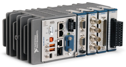
- An NI CompactRIO
- An NI Single-Board RIO (including the NI SOM)
The specs of your application will drive your choice of hardware platform. Of course, you’ll want to be mindful of version compatibility as well.
For embedded applications, you’ll generally want to default to using a cRIO (we love the cRIO and use it a LOT) and let your project requirements convince you that a different platform (e.g. an sbRIO or SOM) is warranted. There’s more details than provided here, but the decision process will usually be based on 3 main criteria (feel free to reach out here if you want to discuss those details):
- Size / envelope – if your application requires a small envelope, the cRIO form factor may just be too big and you’ll be forced to go the sbRIO route.
- Production volumes – at some quantity, it’ll likely make more sense from a financial standpoint to use the sbRIO.
- I/O availability – depending on how much of what you need from an I/O (including comm. interface) standpoint is available either as a module or part of the base unit, the custom board non-recurring engineering design costs may sway you one way or another.
For test system applications, check out our guide Which NI Platform is Right for Your Test Needs? cRIO, PXI, cDAQ, sbRIO?.
Next Steps
Other LabVIEW questions? Check out our LabVIEW FAQ page.
If you work for a US-based manufacturer or R&D lab, go here for next steps:
Use Of Embedded Systems in Industrial Automation
Use Of Embedded Systems in Industrial Automation
Use Cases & Case Studies
Use cases for embedded systems in industrial automation can be divided into two main classes: machine control and machine monitoring.

To make sure we’re on the same page, we’re NOT talking about test system automation. If you’re interested in that topic, please see here.
Use cases for embedded systems in industrial automation can be divided into two main classes: machine control and machine monitoring.
Embedded machine/equipment control – for this use case, the embedded system is controlling some aspect of the industrial machine/equipment. It might be controlling the tight tolerance timing of a particular manufacturing process, it might dynamically adapt production of the part to improve product quality, or it might control the operation of a piece of industrial equipment out in the field. Some examples of machine control applications include:
Machine/equipment monitoring – this could include generalized monitoring of a machine or it could be more focused specifically on condition monitoring, which generally has the objective of improving machine up-time/reliability and/or reducing maintenance costs and production loses. Some examples of machine/equipment monitoring applications include:
If you’re looking for help with using embedded systems for your industrial application, there are two things you’ll want to do to get started: (1) develop a good set of requirements (see here for an industrial embedded requirements template) and (2) find a vendor capable of helping you (check out this Outsourcing Industrial Embedded System Development Guide). If you want to chat about your application with us, you can reach out here.
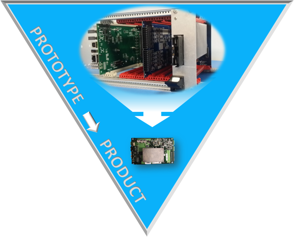
Improving Time to Market for Embedded Systems

Improving Time to Market for Embedded Systems
The design activities are critical to choosing a platform that will achieve the requirements as quickly as is reasonable
The Big Hurdles
When choosing to develop a new product or platform based on an embedded system, companies commit to spending time, money, and resources. There’s an enormous benefit to finishing this development as quickly as possible so that the product or platform can be released to the customers or users as quickly as possible. Fortunately, by using certain tools and methods, companies can in fact shorten the development cycle, and improve their time to market.
I want to make a small distinction between a product and platform. The distinction surrounds the type of user. Embedded systems developed for external use by general customers are labeled as a product. When developed for internal use by specific end-users, it is labeled as a platform.
Don’t minimize the prevalence of these internally-used platforms. I’m including controllers that are used inside a product sold to a customer (e.g., a controller that operates a forklift would qualify, or a condition monitoring device for a gas compressor would qualify).
The key point to be made about these two classes of users is that both need tech support, repair services, upgrades, and so on. So, I’m going to refer to a platform as a product too.
Here is a breakdown of the steps needed to bring a product to market:
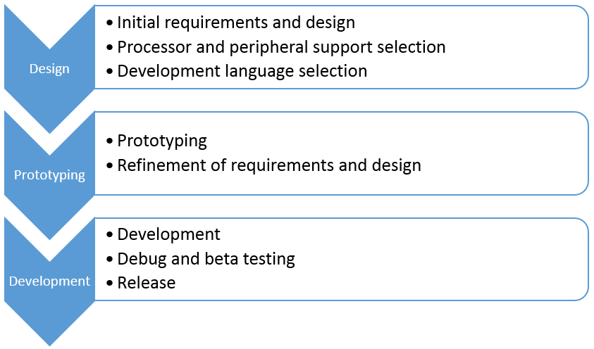
I want to describe each of these items a bit in this post and will do a few “deep dives” in future posts.
As you might imagine, some of these groups associated with these steps are more amenable than others to doing things that improve time to market (TTM). I want to touch on these things quickly and leave some details to those future posts.
The design activities are critical to choosing a platform that will achieve the requirements as quickly as is reasonable. The outcome of this group of steps has a big impact on the TTM.
The prototype activities are also critical to achieving the requirements, but the way they impact the project is in identifying any changes to requirements and design based on the outcome of some initial proof-of-concept-level development and testing. This group is all about failing fast, quickly identifying weaknesses in the component and design choices.
The last group of development activities is less critical to achieving the requirements, and is instead mainly focused on completing the development. There are some tools and techniques that can help speed TTM, but I think these tools have less effect (or maybe a better term is “smaller levers”) than the effect that the other groups have.
So, with that setup, look forward to future posts on design, prototyping, and development when I give you some ideas to speed TTM for embedded systems.
Want more information on developing embedded systems? Read our white paper “Top Five Embedded System Design Fails.”
Tips for Reducing Embedded Prototyping Costs
2 Tips for Reducing Embedded Prototyping Costs
In just about every industry there is a drive to reduce cost when bringing new products to market. With regard to the world of embedded design, there are a few things that have been proven to consistently allow for teams, both big and small, to reduce the cost and time associated with new widgets.
To address some of these challenges, we’ve developed an ecosystem for embedded development called VERDI, to help reduce engineering costs and development risk
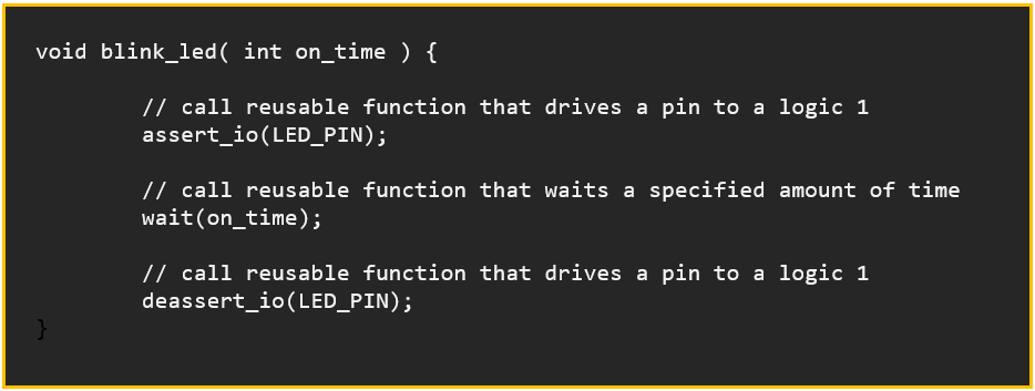
Tip 1 for Reducing Embedded Prototyping Costs – Reuse. Reuse. Reuse.
In the world of software (embedded or not), coders do their best to prevent copy and pasting code. We do this by creating reusable code blocks (commonly referred to as functions, but come in a variety of different names) that can be called upon to perform tasks by various different parts of the system. Examples would include converting between data types, performing complicated file IO, or manipulating data structures.
This reuse in code provides a few different things that make the coders’ lives easier:
- If the functionality of the code snippet has to change, you only have to change it in one spot.
- You don’t risk “copy pasting” errors by having very similar code all over with just slight differences.
- Testing complexity is significantly reduced.
Reusing code is usually a pretty easily understood concept, and thus is implemented most computing projects.
The other aspect of reusability to consider is the hardware perspective. This is commonly accomplished with libraries of components (Integrated Circuits, passives, interconnects, stencil artwork, etc.). Most embedded engineering teams have amassed quite the library of hundreds, thousands, or even tens of thousands of components that they have used over the years in their projects.
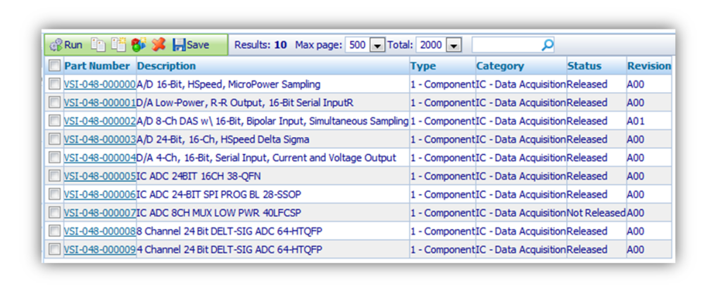
Organizing that many components can really be a challenge. There are, luckily, a number of software providers that assist with managing this sea of schematic, layout, and mechanical drawings. Some even allow for parametric search and meta-data assignment for internal use. The *really* good ones help with BOM export/management so buyers aren’t flying blind when they go to actually purchase the components that designers put on the boards.
Wait, aren’t we talking about saving money? Those tools sound expensive …
Tip 2 for Reducing Embedded Prototyping Costs – Yea. Tools cost money. So does not buying them.
I think my biggest trick for saving money in embedded designs is not cutting corners with tools for the design team. Too many times I’ve heard things like:
“ … we didn’t buy the debugger because it was $1,100, and we didn’t have that in the budget”
or
“ … we rented the cheapest scope we could for 6 months, because the engineers insisted we get one.”
Meanwhile they’re 6 weeks past their final milestone because there was a null pointer reference deep in their SPI Flash library, or they couldn’t see the overshoot on their clock because the scope only had 500 MHz of bandwidth. Sure, Michelangelo probably would have been able to paint the Sistine Chapel with a toothbrush, but for the rest of the artists out there, spending the money on high-quality brushes helps them produce a higher-quality output product. Engineers and their tools are no different.
The next level of reuse is entire hardware designs, not just the single components within them. Although it does happen that hardware designs do not use software, with the increased complexity of ICs on the market hardware designs are becoming more and more depending on software to work correctly. This pairing of hardware and software in reusable, modular packages allows for massive reductions in cost and risk.
Pulling from a library of proven hardware designs is not uncommon when moving between versions of products, or producing tech refreshes for existing product lines. This, of course, requires the team to first create the product from scratch, and then build off of it. Sounds great, but building up that library to pull from can be hundreds of thousands to millions of dollars – even for a small library.
To address some of these challenges, we’ve developed an ecosystem for embedded development called VERDI, to help reduce engineering costs and development risk. Check it out and let us know what you think:
When Is an FPGA Worth it and When is it NOT – when developing an Industrial Embedded System – Part 2

When Is an FPGA Worth it and When is it NOT – when developing an Industrial Embedded System – Part 2
Simulation environments for FPGAs are generally pretty solid, but you eventually have to move into hardware, where your visibility into what’s going on decreases significantly
In part 1 of this article, we introduced some well-suited applications for FPGAs, and highlighted some strengths and weaknesses of FPGAs. Now we transition over to some cautionary elements of utilizing FPGAs.
Some Things to be Mindful Of

Traditional development environments that tend to utilize text-based languages such as VHDL and Verilog are NOT for the casual user. The languages and the tool chains have a steep learning curve and the tool chains can be expensive.
Debugging tools –
The disadvantage of a run-of-the-mill sequential processor is that only one operation is executing at any point in time. The advantage of a sequential processor is that only one operation is executing at any point in time. When it comes to debugging, this sequencing makes life easier than debugging an FPGA. Simulation environments for FPGAs are generally pretty solid, but you eventually have to move into hardware, where your visibility into what’s going on decreases significantly. You can view outputs of course, and you can create test points, but you have to be able to probe all of those points, so you’ll need a logic analyzer, which can get very pricey. You may be able to get away with embedding test resources into your device (e.g. Xilinx has the Integrated Logic Analyzer), but this will utilize FPGA logic and memory resources, and is often challenging to see enough breadth or depth about what’s going on inside your FPGA. However, generally these tools are better for augmenting a true logic analyzer, as opposed to replacing them outright.
Cyber security –
A lot of FPGAs are embedding Ethernet cores, common processor cores, and some are even running an OS, making it so FPGA-based (sometimes referred to as SoC (system on a chip)) solutions look like another computer on the network. This opens up their vulnerability to more traditional attack methods. Take the time to understand your risks and mitigate them. Obscurity is generally NOT a solid security approach (check out The Great Debate: Security by Obscurity). Here are two articles to get you thinking:
- How to build an FPGA-based I&C
- Microsemi Steps Up Its Cyber Security Leadership in FPGAs: SmartFusion2 SoC FPGAs and IGLOO2 FPGAs Enhanced with Physically Unclonable Function Technology
Safety –
If you’re considering an FPGA-based system for a safety-related function, you need to understand the risks that you’re incurring. Here are a few articles to get you thinking:
- Safe FPGA Design Practices for Instrumentation and Control in Nuclear Plants
- SRAM-Based FPGA Systems for Safety-Critical Applications: A Survey on Design Standards and Proposed Methodologies
- Xilinx Reduces Risk and Increases Efficiency for IEC61508 and ISO26262 Certified Safety Applications
Where You Might Head From Here:
Hopefully these thoughts have given you some things to chew on. If you decide it might make sense to proceed with an FPGA-based embedded system and don’t have the time or manpower to create your own solution, check out VERDI. If you’re interested in other industrial embedded system info, check out our resources page.
When is an FPGA Worth it and When is it NOT – when developing an Industrial Embedded System – Part 1

When is an FPGA Worth it and When is it NOT – when developing an Industrial Embedded System – Part 1
As FPGA prices continue to drop, I speculate we’ll see more and more advanced industrial equipment and machines (with particular needs) taking advantage of FPGA-based systems
So you keep hearing about FPGAs being utilized in more and more applications, but aren’t sure whether it makes sense to switch to a new technology. Or maybe you’re just getting into the embedded world and want to figure out if an FPGA-based system makes sense for you or not.
One of the first questions you should be asking yourself on this topic is: relative to what? What are we comparing an FPGA-based solution to? Mostly we’re comparing to scenarios where general-purpose microprocessors or microcontrollers are being considered as the alternative technology.
Well-Suited Applications
Historically, FPGAs were VERY expensive (like up to thousands-of-dollars-per-chip, expensive), which limited the applications that utilized FPGAs to VERY expensive systems, such as military and aerospace systems. See Wikipedia – FPGA Applications for more use cases.
As FPGA prices continue to drop, I speculate we’ll see more and more advanced industrial equipment and machines (with particular needs) taking advantage of FPGA-based systems. Here are a few that we’ve seen:
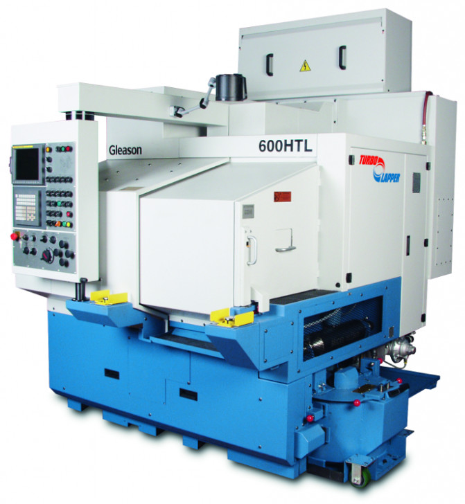
- Industrial machine – Gear lapping
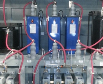
- Electrical Energy – VAR compensator
- Structural health monitoring – Railroad viaduct
- Electrical Energy – Remote monitoring
- Electrical Energy – Generator Condition Monitoring
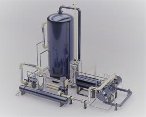
- Industrial Equipment – Compressor Condition Monitoring
FPGA Strengths/Best Suited:
Much of what will make it worthwhile to utilize an FPGA comes down to the low-level functions being performed within the device. There are four processing/algorithm attributes defined below that FPGAs are generally well-suited for. While just one of these needs may drive you toward an FPGA, the more of these your application has, the more an FPGA-based solution will appeal.
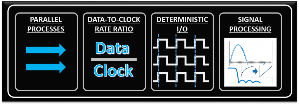
- Parallel processes – if you need to process several input channels of information (e.g. many simultaneous A/D channels) or control several channels at once (e.g. several PID loops).
- High data-to-clock-rate-ratio – if you’ve got lots of calculations that need to be executed over and over and over again, essentially continuously. The advantage is that you’re not tying up a centralized processor. Each function can operate on its own.
- Large quantities of deterministic I/O – the amount of determinism that you can achieve with an FPGA will usually far surpass that of a typical sequential processor. If there are too many operations within your required loop rate on a sequential processor, you may not even have enough time to close the loop to update all of the I/O within the allotted time.
- Signal processing – includes algorithms such as digital filtering, demodulation, detection algorithms, frequency domain processing, image processing, or control algorithms.
Weaknesses/Non-Optimal:
With any significant benefit, there’s often times a corresponding cost. In the case of FPGAs, the following are generally the main disadvantages of FPGA-based solutions.
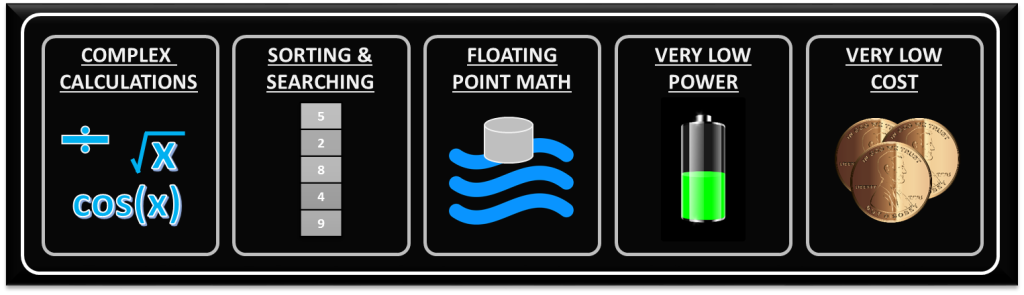
- Complex calculations infrequently – If the majority of your algorithms only need to make a computation less than 1% of the time, you’ve generally still allocated those logic resources for a particular function (there are exceptions to this), so they’re still sitting there on your FPGA, not doing anything useful for a significant amount of time.
- Sorting/searching – this really falls into the category of a sequential process. There are algorithms that attempt to reduce the number of computations involved, but in general, this is a sequential process that doesn’t easily lend itself to efficient use of parallel logical resources. Check out the sorting section here and check out this article here for some more info.
- Floating point arithmetic – historically, the basic arithmetic elements within an FPGA have been fixed-point binary elements at their core. In some cases, floating point math can be achieved (see Xilinx FP Operator and Altera FP White Paper ), but it will chew up a lot of logical resources. Be mindful of single-precision vs double-precision, as well as deviations from standards. However, this FPGA weakness appears to be starting to fade, as hardened floating-point DSP blocks are starting to be embedded within some FPGAs (see Altera Arria 10 Hard Floating Point DSP Block).
- Very low power – Some FPGAs have low power modes (hibernate and/or suspend) to help reduce current consumption, and some may require external mode control ICs to get the most out of this. Check out an example low power mode FPGA here. There are both static and dynamic aspects to power consumption. Check out these power estimation spreadsheets to start to get a sense of power utilization under various conditions. However, if low power is critical, you can generally do better power-wise with low-power architected microprocessors or microcontrollers.
- Very low cost – while FPGA costs have come down drastically over the last decade or so, they are still generally more expensive than sequential processors.
Some Things to be Mindful Of
Stay tuned for part 2 of this article, where I’ll throw out the caution flag and highlight some areas to be mindful of, revolving around debugging tools, cyber security, and safety.
Where You Might Head From Here:
Hopefully these thoughts have given you some things to chew on. If you decide it might make sense to proceed with an FPGA-based embedded system and don’t have the time or manpower to create your own solution, check out VERDI. If you’d like more useful info on industrial embedded systems, check out our resources page here. You can check out part 2 of this article here.
The Embedded Design Checklist – For New Designs

The Embedded Design Checklist – For New Designs
It’s easy to just assign tasks to the team based on approximate time-loading, however this can be troublesome in a number of ways
Beginning a new embedded design is both exciting and daunting. There are many aspects of starting a new design that are fun and engaging, however it’s important to step back and make sure you’ve made the right decisions and assumptions up-front, to reduce headaches later. Below is a simple checklist you can use when starting a new design.
Does everyone have a firm grasp of the scope of the project?
Most embedded projects seem simple when designing on the white board, but it’s often the case that large parts of the design aren’t yet known, or are not well communicated to the system architect. Make sure you work with your external customer(s) as well as your internal team to ensure all stakeholders have a firm grasp on the scope of the system. One of the worst phrases you can hear at demo time is “well, where is feature X?”.
Does everyone know their role?
It’s easy to just assign tasks to the team based on approximate time-loading, however this can be troublesome in a number of ways. Since each member of your team probably doesn’t have the exact same skill sets, the team should work together to best understand which tasks are the best fit for each member. It is, of course, important to continue to challenge yourself and team members, however if the project isn’t going to say on budget because a member needs to learn too many skills to complete a task, that doesn’t make sense. This touches on the next checklist item …
Does everyone have the training they need?
Not every new design is going to be “cookie cutter”. It’s very possible that a customer ( internal or external ) requires your new design to use a technology that no one on your team has experience in. This could be as simple as a transmission protocol, or as complicated as a brand new processor, DSP, or FPGA platform/architecture. It’s important to understand what training may be needed, build that cost into the project, and set expectations appropriately with all stakeholders associated with the project on how long it may take to bring everyone up to speed on the new technology.
Has someone done a ‘back of the napkin timeline’?
A big part of engineering is sanity-checking your decisions ( calculations and assumptions ) with estimation. You should always be able to look at a design or problem and get a rough order of magnitude of how large of a problem this is ( this statement obviously falls apart for very large programs such as the space shuttle, but for the argument of this blog post let’s assume this is just for embedded devices and smaller ). Being able to understand what the goal timeline, and what a realistic timeline ( and hopefully those match up closely ) is, will help you continue to set expectations with stakeholders, and better work with your team to meet milestones. There will always be projects that end up behind schedule and will be stressful. However, by having an understanding of what a possible timeline is before starting the project can greatly help reduce stress going in.
Do you have a block diagram?
Spend some time with a whiteboard and your team. Get everyone in the same room with a large, blank whiteboard and go to town. Start with the central processing IC ( Processor, DSP, FPGA, SoC, etc. ), and move outward. Most embedded systems need Memory ( both volatile and non-volatile ), power management, and communications ports. Additional components might include Analog to Digital and Digital to Analog converters. Get as much of the system down onto the Whiteboard as you can, and then start taking pictures. It is also a good idea to have a dedicated note taker for each meeting, and have those meeting notes posted for all team members to see ( it may also be appropriate to send these notes and the block diagram to other stakeholders ).
Has the team settled on what Software Tools will be used?
More than likely everyone on your team is going to be using a computer. And on those computers will be software that will help team members complete the tasks that are assigned to them. Projects live and die based on what software packages and technologies they use. In some cases the software you will be using will be picked for you by the silicon vendor you are using ( you’re going to be working with Vivado if you use Xilinx, or LabVIEW if you use National Instruments ). Other cases you may have a choice. It’s important to have your team spend time between projects working with different software packages so they know which ones work well and which ones are just garbage. By encouraging team members to always be trying new software packages, you are more likely to settle on one that is the right fit for your needs when a new project comes in the door. Additionally, if you have been using the same software package for 5 years or more, it’s probably time to revisit the marketplace to see what innovations have been made in the last half decade.
Have we bitten off too much to chew?
“I know it’s only two months, but do you think you can get this done by October?”. This is the kind of question that often comes from stakeholders ( internal and external ) from management all of the time. Those inside and outside of your team often are going to be pushing you to be a little bit smarter, a little bit faster, and a little bit cheaper. That’s their job. It also can be super stressful and frustrating (especially when they know darn well that it’s an unrealistic request). Sometimes there is just too much work to be done in the timeframe that you’re given (that’s why “Has someone done a ‘back of the napkin timeline’?” is so important). You’re options are usually:
- Push back right away rather than let stakeholders think that their request was reasonable
- Fold, and just try your best to get it done ( this is, obviously, the least desirable since it results in long days and a grumpy team )
- Outsource/subcontract a portion of the project that you know is an easy bite-sized chunk that your team can quickly define.
The third option does not come without headaches – so don’t think it’s always the answer. It can, however, allow work to be done by a contractor in parallel with your team, thus making the unrealistic deadline a little bit more realistic.
So above is my quick New Embedded Design Checklist. The above items, along with reading datasheets, talking with suppliers, and ( sometimes far too many ) team meetings is how I start each new embedded design. If you’d like to chat more about starting a new design, and how I or Viewpoint Systems might be able to help, feel free to drop us a line. If you’d like to learn more about embedded design considerations, check out this white paper on the Top 5 Embedded System Design Fails. If you’d like more industrial embedded info, check out our resources page.
Some Tips to Speed Up Industrial Embedded Product Prototyping

Some Tips to Speed Up Industrial Embedded Product Prototyping
If you have not found an optimal platform, then you are likely working with tools that are functionally equivalent to your end goal but not in the desired form
Recall from the initial introductory post on the topic of improving Time to Market, I introduced three stages in a typical product development process: Design, Prototyping, and Development.
This post will focus on the Prototyping stage for industrial embedded systems.
I broke down this Prototyping stage into two major components. See the chart below for reference to all the stages. Two stages are grayed out to highlight the one covered by this post.
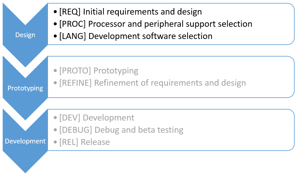
Variations of this chart have been included in all the posts so far.
Setup
Recall from the prior post on the Design stage that the hypothetical company already has a product out in the market which is electromechanical in nature (it interfaces to stuff like valves, motors, sensors, …). About a couple 100 of these units are sold per year.

When entering this Prototyping stage, the hardware and software tools have already been selected in the previous stage and these tools need to be proven for basic functionality. The purpose of this stage is to design enough of the system that the team feels assured that all the requirements can be met with these tools. You don’t need to especially don’t or want to do the entire development in this stage – just enough to be confident that you can complete the development. Prototyping is entirely meant to reduce project risk.
Often, however, the tools either 1) can’t meet one or more requirements or 2) the time and cost of achieving those sets of requirements is onerous. This situation leads to a refinement step, where the design and tools are evaluated against the requirements and give-and-take adjustments are made to both the requirements and tools to assure that the design will meet all the needs of the product while staying within reasonable time and cost budgets.
Prototyping
If you have followed the tips in the post on the Design stage, you have found a platform which is an optimal combination two goals: 1) being closest to your end goal in form and function and 2) requiring the smallest amount of NRE development effort. The intent of these goals is to let you prototype the product on the same platform (hardware and software) that you will use in the development of the product. Or, turned around, if you prototype on a different platform (either hardware or software or both), then additional work is needed to convert to the product platform.
If you have not found an optimal platform, then you are likely working with tools that are functionally equivalent to your end goal but not in the desired form. In fact, this situation is perfect when there are too many unknowns in the design of the product, such as which actuators and sensors the controller will interface with, much less if your idea will work at all. (Maybe you are actually doing R&D instead?)
I’ve also seen some companies enter the Prototyping stage with little or no off-the-shelf hardware. These companies plan to develop the final form of the hardware before prototyping. This effort includes the design and layout of all the custom circuitry, connectors, power supplies, and so on. The justification is that they can say they prototyped the system in its actual final configuration. But there is risk involved in this approach UNLESS they have absolutely no question about the system working as required. But if there is no question, then they’ve essentially skipped the Prototype stage and gone direct to the development stage. In my opinion, this approach ignores the risk-mitigation benefits of prototyping. Prototyping before development is always the better method.
As mentioned earlier, the best plan uses an optimal combination of form and function closeness with a small amount of NRE. This plan likely takes pre-developed hardware (controller and I/O) in combination with a software development environment that natively supports this hardware.
Using this combination for the Prototyping stage will reduce the effort in either 1) designing your own custom circuitry in order to prototype or 2) having to morph the prototyping hardware and software into the form you need for your product.
To get a sense about the savings available with such a combination, I’ve included the bar chart from the Design stage post to show my estimated time/cost savings for the hypothetical project. To achieve these savings, I chose the VERDI platform. It is based on the NI SoM RIO controller that will be used in the product. I can also obtain all the off-the-shelf I/O that I need for the product (e.g., thermocouple input and 24 V digital output). Finally, the system supports LabVIEW for software development.
Consequently, since the PROTO step will be done on the same platform as the product, there won’t be any additional hardware and software changes in the Development stage, which minimizes the risk that any updates to design and requirements will affect the end product.
For the cost/time savings in the PROTO step, I’ve estimated 50% of the effort that would have otherwise been spent if the platform chosen for prototyping used that was different than the one used for development. See the bar chart for details.
Peeking ahead, note in the bar chart that I spend a nearly as much time in the PROTO step as in the DEV step (in the Development stage). This level of effort in PROTO is not uncommon if you want to be really confident that there will be no surprises in the Development stage. (“What!?!? … I can’t do that???”.) Specifically, I want to spend effort to clearly identify and justify any changes made in the REFINE step.
Refine
Based on the outcome of the PROTO step, I’ve included time for the REFINE step to make adjustments in the requirements and design (in both software and hardware). With those adjustments made, the team can be confident that the project can be completed in a reasonable time and cost with the selected hardware and software.
Since this refinement step is needed regardless of the prototyping platform choice, there is no time/cost savings to be had in the REFINE step. See the bar chart for details.
Some Tips to Speed Up Industrial Embedded Product Development

Some Tips to Speed Up Industrial Embedded Product Development
This post will focus on the Development stage of an industrial embedded system.
Recall from the initial introductory post on the topic of improving Time to Market, I introduced three stages in a typical product development process: Design, Prototyping, and Development.
This post will focus on the Development stage of an industrial embedded system.
I broke down this Development stage into two major components. See the chart below for reference to all the stages. Two stages are grayed out to highlight the one covered by this post.
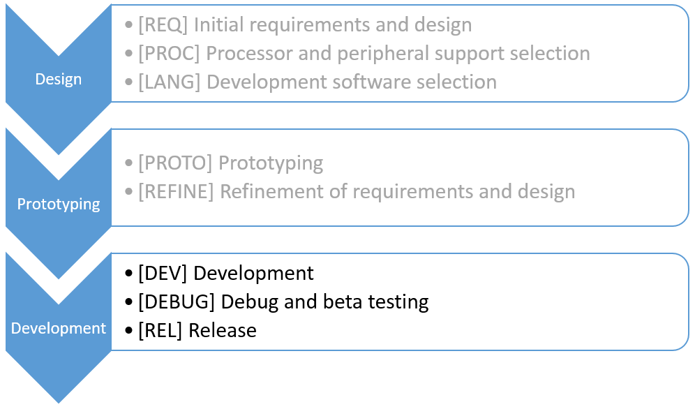
Setup
Recall from a prior post, about the Design stage, that the hypothetical company already has a product out in the market that needs to be upgraded. The product is electromechanical in nature (it interfaces to stuff like valves, motors, sensors, …). About a couple 100 of these units are sold per year.

Also, remember that this series of blog posts has been discussing these stages relative to comparing various hardware and software platforms. Since we are going to replace the existing obsolete controller, I’m considering 3 approaches to replace this old controller.
The first approach starts with a completely COTS hardware approach and ends with a custom hardware (single board) solution. The second approach starts with completely custom (single board) solution and uses that hardware through the whole product development cycle. Finally, the third approach starts with a COTS controller and combines that controller with both COTS and, if needed, custom I/O hardware. I label this approach as “Hybrid” since it considers both COTS and custom hardware.
IMPORTANT CHANGE OF PLANS: Note that in prior posts, I’ve only compared the Hybrid approach with a sort of merged COTS & Custom approach. But, while writing this post, it became clear to me that I really needed to differentiate the purely COTS and Custom approaches since they are so different when comparing the amount of time each spends in the PROTO and DEV steps. So, I’ve expanded the comparison bar chart below to make these differences clearer by reviewing 3 distinct approaches.
You might remember from the design post that options for this hybrid approach are many. Back in that earlier post, I recommended that you look for a platform that uses components close to the same physical form of your end goal. One example is the PC/104 standard. Utilized for decades (i.e., since 1992), it has now evolved to support the PCIe bus. Another option worthy of consideration is the VERDI platform, based on the NI SoM RIO controller and several pre-developed I/O hardware modules. Finally, on the low end, the Raspberry Pi and Beagle Boards offer some pretty amazing capability for a very low price – the downside being that this hardware is not as industrially robust as the others (e.g., the BeagleBone and RasPi have no heat spreader whereas the NI SoM RIO does).
OK, now that I’ve done this “overview”, let’s talk about the Development stage.
Development
After completing the Prototyping stage, the Development stage picks up after the hardware and software designs for this updated product have been vetted and the team is ready to begin creating the actual product. The Development stage contains the DEV and DEBUG steps which are intended to assure that the product is functioning as desired and doing so robustly. Also, very importantly, this stage includes the REL step for assuring that the product documentation is completed and archived and the product is ready for manufacturing. This REL step is boring but saves you from the embarrassment and frustration when you need to make a revision in the future and can’t find the layout files! Such a simple step but so important too.
Check out the bar chart below. The biggest point I want to make in this chart (and the reason I explicitly describe the 3 hardware approaches) is the inherent tradeoff between prototyping and development. Specifically, when the hardware used to prototype is different than used to develop, a lot of time is spent in either PROTO or DEV, but not both.
For example, if following the Custom approach, then the effort in the PROTO step is much more than if I were using COTS hardware. And, vice versa for the DEV step with COTS since there is a large effort to convert the functionality of the COTS hardware into custom hardware.
For the platform that starts with a COTS controller and as much pre-developed I/O hardware as possible, much if not all of this same hardware can be used in both PROTO and DEV steps. Consequently, I can choose to split the effort across those two categories, as illustrated in the bar chart. (Remember the sum of all the blue Hybrid bars totals 100%).
Finally, by way of comparison, experience shows that developing a Custom hardware solution from scratch takes something like 4X the time that is takes to combine pieces of pre-developed hardware modules from the Hybrid platform into a custom single board.
All these observations are illustrated in the bar chart which shows radically different bar lengths in PROTO and DEV for the three different approaches.
Interestingly, when following the Custom approach, the DEV step effort might be reduced relative to the Hybrid level. Why? Because all that hardware developed in the PROTO step would have been used exactly as is in the DEV step without any redesign, whereas the Hybrid approach would need to take the pre-developed I/O from each module and layout all that modular HW onto a single board.
CAVEAT: This benefit of Custom over Hybrid in the DEV step assumes no rework is needed on the Custom approach after the PROTO step is completed, a potentially unlikely scenario since so much information is discovered during the PROTO step. Rather, it is often the case that the DEV step with Custom is larger than the Hybrid case due to unexpected hardware redesign.
Even with the Custom approach, the blue bar for DEV would still not be zero length because the software created during the Prototype stage is not product-worthy, being temporary and somewhat hacked together to show functionality as quickly as possible.
In summary, the three scenarios considered are 1) Hybrid platform (COTS controller, pre-built custom I/O), 2) completely Custom, and 3) completely COTS. Then, the combination of time spent in the PROTO and DEV steps might be as shown in the table below.
| Scenario | PROTO | DEV | Total |
| All COTS | 23% | 100% | 123% |
| All Custom | 115% | 23% | 138% |
| Hybrid (COTS + Custom) | 23% | 31% | 54% |
The key takeaway in this table is that you can save time (and cost) by passing thorough the Prototyping stage as quickly as possible by utilizing previously developed hardware. And, if that same hardware is also used for the Development stage, significant time (and money) is saved.
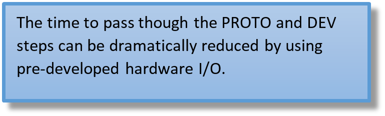
One downside of a Hybrid platform appears in the PROTO step. If the COTS controller and pre-developed hardware does not have the type of I/O needed for the PROTO step, then the COTS approach will certainly be best for PROTO since that platform likely has all the I/O you need.
Another way to describe the lesson in this table is that designing custom hardware takes effort and cost. When a hybrid COTS and pre-built I/O can be used both for prototyping and development, you win.
Note that these numbers don’t include any costs associated with the actual hardware, which would be substantially larger in the ‘All COTS’ scenario than the ‘All Custom’ scenario.
Debug and Beta
When the DEV step is done, the application is ready for debug and testing. No matter which approach you use in the COTS vs Custom spectrum, you will need debugging. Consequently, as shown in the bar chart above, I’ve given each of the 3 approaches roughly the same schedule, with a slight advantage to the approach that uses pre-developed hardware since there will likely be fewer last-minute tweaks to the hardware I/O. Check out some suggestions for debugging techniques.
After you’ve debugged the system, you should have various users try your system to see if they can break it. Good beta testers take pleasure in breaking your stuff.
In the end, there is just no way around this DEBUG step of debugging and beta testing and hence not much can be done to shorten the time.
Release
After the testing steps, you are ready to release the product to the manufacturer. This is the time to complete the configuration management of your system, such as labeling or tagging the version of your software, assuring that all the documentation (e.g., BOM and drawing package) is complete, before releasing your product to production.
At this REL step, the actual hardware platform selected does not affect the effort much, and I’ve given each of the 3 approaches the same time to complete.
As with the DEBUG step, not much can be done to reduce the amount of time on this step. If you’re interested in learning more about industrial embedded systems, check out our resources page.
Some Tips to Speed Up Industrial Embedded Product Design
Some Tips to Speed Up Industrial Embedded Product Design
My recommendation? Look for a platform that uses components close to the same physical form of your end goal
Recall from the previous post on the topic of improving Time to Market, I introduced three stages in a typical product development process: Design, Prototyping, and Development.
This post will focus on the Design stage.
I broke down this Embedded Design stage into three major components. See the chart below for reference to all the stages. Two stages are grayed out to highlight the one covered by this post.
This chart was taken from the previous post and modified to add some labels, such as “[REQ]”, for quick reference to the specific items. (Also, I changed “language” to “software”.)
Setup
To make this post (and subsequent posts on this topic) more relevant, I have in mind a hypothetical project for a company that already has a product out in the market. This embedded product is electro-mechanical in nature, meaning that it needs to interface to stuff like various sensors (voltage, temperature, …), valves, motors, and so on. The company expects to ship a couple 100 of these units per year.
The existing product needs to be upgraded due to obsolete or hard-to-get components. In addition, the product needs a refresh. For example, the present model has no Ethernet port for data downloads or remote operation. Some other user interface and operational features need to be added as well.
The point is that the company already has a good starting point for requirements, based on the existing model, for the upgraded product. Contrast this situation with a completely new concept which has a blank whiteboard just waiting for requirements. Clearly the time expended on requirements gathering on the upgrade will be less than for a brand-new product.
With this hypothetical project in mind, refer to the chart below, which shows time spent on the project relative to the time reduced by using ideas and tools I will recommend in this post.
The “%Effort” bars show the estimated time using the recommendations in this blog series. The “%Reduction” bars show estimates for the additional effort it would take if the often-traditional approach is used. The “%Effort” bars sum to 100%. The “%Reduction” bars sum to an additional roughly 90% more work.
Requirements
The project engineers need to know what they are building. The sales and marketing team needs to know what they are trying to sell. So, the company needs to document the product requirements. I can’t think of any good tips on reducing this effort – it just needs to happen. Hence, the REQ step has no bar for reducing the effort.
Processor & Peripherals
Proper choice of processor and peripherals can certainly save time and effort. Familiarity of a processor and all its support tools has a large effect on making the product development cycle shorter. This choice can be very complex and time-consuming because there are so very many options. The choice of peripherals is large too. Deliberations about mixing and matching all these items with all the pros and cons takes considerable time.
However, if you consider a solution based on a processor board with many peripherals already designed in, much time can be saved. One such solution is the sbRIO board from NI.
Almost certainly, the unit cost price point would be higher for this “pre-developed” approach, than a board you spin completely anew. However, our hypothetical product contains so many other costly components that it makes sense to emphasize getting the upgraded product to the market sooner than to shave say 50% off the price of the controller alone (i.e., which contributes maybe a couple % of overall system cost).
Find a platform that is closest to your end goal in form and function that also requires the smallest amount of NRE development effort.
The same is true for analog, digital, and other I/O boards. Using “pre-developed” I/O hardware will speed development.
Going down this “pre-developed” path is tried and true. One that addresses enclosure and connectivity needs, is the Compact RIO from NI. This platform is robust, industrial, and solid. But note that this hardware is typically the most expensive option.
Among the maker-movement, which certainly has strong market-direction influence, are the Arduino and the Raspberry Pi platforms each with pre-developed controller boards and I/O hardware. Unfortunately, these “maker” solutions may not be robust enough for industrial applications.
My recommendation? Look for a platform that uses components close to the same physical form of your end goal. One example is the PC/104 standard. Utilized for decades (i.e., since 1992), it has now evolved to support the PCIe bus. Another option worthy of consideration is the VERDI platform. VERDI offers pre-developed I/O hardware and uses the NI SoM RIO for the controller.
Obviously, when choosing a “pre-developed” controller and associated I/O hardware based on off-the-shelf components, you trade off higher unit costs for lower non-recurring engineering (NRE) development costs. So, the best tip I can make is to find a platform that is closest to your end goal in form and function that also requires the smallest amount of NRE development effort.
In the bar chart above, I’ve chosen an NI processor (SoM RIO) which has a lot of the connectivity I need. By using this off-the-shelf product, I don’t have to spend a lot of time searching for all the parts. I’ve spent an estimated 30% of the effort that I would have had to otherwise spend researching all the options and support component parts.
(When I wrap-up this blog series, I’ll show you an illuminating diagram that summarizes platform choices in a way that nicely captures the evolution of a unit costs as each year (hopefully) brings higher sales volumes which allow unit costs to be driven lower. This chart really drives home the need to start with components close to the end goal. Stay tuned.)
Development Software
Obviously, the OS and development software have to be compatible and well-supported with the controller and I/O you select. Yes, there are lots of options here too, but most of the choices quickly settle into Windows vs. Linux, for the OS, and text-based vs. graphical programming, for the development software.
Linux is more prevalent in the embedded market place, but interestingly Microsoft is making significant progress their Windows IoT Core aimed at Arduino, ARM, RasPi, and other “tiny” platforms. This effort is an outgrowth of the Windows Embedded platform Microsoft has had for many years. Microsoft also has Azure, a full-featured cloud platform. So, you have choices.
Much of programming software choice is seemingly based on almost religious reasons (i.e., either you believe or you don’t), and this preference may so strong as to even drive your hardware selections.
…the graphical approach is generally faster to develop and easier to debug.
Nevertheless, based on experience using both text and graphical languages, my recommended tip is that the graphical approach is generally faster to develop and easier to debug. Hence, I generally prefer LabVIEW. I recognize that this choice drives me toward NI hardware solutions, but the tight integration between the software and hardware is also a bonus in reducing Time to Market, as compared with combining disparate hardware and software solutions offered by separate companies.
In the bar chart above, I’ve chosen LabVIEW which provides the development tools that I need. Also, since LabVIEW works with the SoM RIO hardware platform, I don’t have to spend a lot of time making sure that my software tools will work with my hardware. I’ve spent an estimated 50% of the effort that I would have otherwise spent researching OS and software development SDKs. If you’re interested in learning more about industrial embedded systems, check out our resources page.
So I hear you’re working on a project …
So I Hear You’re Working On A Project
An engineer or a project lead has a seemingly endless number of things to keep track of and develop when starting a new project or program
Technical Marketing Person:
“How’s the turbo-encabulator demo coming along? Are you going to be demoing the inverse reactive current for the unilateral phase detractors?”
Engineer:
“Um, no … I don’t remember seeing inverse reactive current for unilateral phase detractors in the requirements document …”
Some of us have been there (hopefully you have not!) the moment when someone from marketing asks if a feature has been included in the demo spec, and it hasn’t. Even worse, the question comes at nearly the end of the project. And the first thing you think is: “How did this happen?”
An engineer or a project lead has a seemingly endless number of things to keep track of and develop when starting a new project or program. A big part of engineering is solving technical problems, but there is a whole other dimension of less technical things that you should consider.
Requirements. Requirements, requirements, requirements! Getting specifications and project details from customers and stakeholders can be a really painful and stressful part of any project – technical or not. BUT, once those requirements are documented and agreed upon (even if they evolve over time), it helps reduce situations like the one above with our turbo-encabulator.
People. They’re everywhere. You work for some of them, and perhaps some of them work for you. Either way, you are all working with each other to get to the solution to a specific problem (or a large number of problems). Communication between team members really is super important. If you’re a leader, make sure you work to identify what your team members’ strengths and weaknesses are, and suggest different tools and methods to better themselves – especially if it’s communications skills. If you are working with the team, always work on bettering yourself as an engineer and as a communicator – take classes, solicit feedback at review time, and review your previous correspondences to make sure that what you thought you communicated actually was received that way.
Resources. Although you work with people, in some cases, it’s important to look at people like they are resources. You would not, of course, pick a 110V relay for your 280V design, or use twine to attach your communications satellite wire harness to the frame. In engineering we are presented (sometimes relentlessly) with different tools to pick from when solving problems. We spend quite a bit time researching and learning those new tools to help us pick the right ones for our particular project. We should apply this same level of rigor to picking people when assigning tasks on projects. You wouldn’t put your material scientists in charge of picking what embedded software framework to use, so don’t pick people to solve problems that they aren’t good at solving. Work within your team to decide which tasks are going to be taken on by which members.
I really enjoy working in teams, and learning to better understand what my team is and isn’t good at. As an engineer, I love problem solving. And if I’m given a puzzle of different personalities, skills, abilities, and passions, I look forward to the optimization problem ahead of me at the beginning of each new project!
Want to read more about this topic? Check out this white paper I put together on the “Top 5 Embedded System Design Fails – Common Pitfalls and How to Avoid Them”.
Six debugging techniques for embedded system development

Six Debugging Techniques for Embedded System Development
Developing embedded systems can be a ton of fun. However, the debugging process often induces a lot of unneeded stress. With the right resources, time, and techniques, the debugging process can actually be a lot of fun as well. We recently published an article in Control Engineering which discusses some helpful techniques: Six debugging techniques for embedded system development. If you like what you see, sign up to receive more helpful information from Viewpoint.
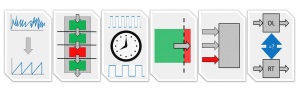
Reduce Development Cost and Risk with a SOM-based approach for Industrial Embedded Designs

Reduce Development Cost and Risk with a SOM-based approach for Industrial Embedded Designs
One of the biggest ways to reduce engineering development costs and risk is by utilizing existing hardware and software whenever possible
You’ve got a great idea for a new smart industrial machine, instrument, or piece of equipment that you think has a good chance of doing well in your industry (okay, maybe it’s not as sexy as designing the Model S or the new iPhone, but in your world, this is a pretty cool idea you’ve got). You know you’re on to something because you’ve lived in your domain long enough to recognize real pain when you see it.
Now you need to actually make the thing. You’ve talked to some people you know that you think fit your target customer profile wonderfully. You get them all excited, a few of them excited enough to actually give you some money to be early adopters and try the thing out. Now the race is on. You know it’s important to be successful out of the gate. You don’t have a ton of time, and you sure didn’t get enough money to plan for 10 years down the road. You need to bootstrap yourself and get the thing out the door yesterday!
Maybe you have a pretty good handle on the mechanical aspects, the algorithms, and the sensors, but you either don’t have the background, or maybe you just don’t have the manpower, to tackle the embedded electronics hardware and software.
Read on to learn how you can reduce engineering costs (AKA non-recurring engineering or NRE) and development risks with a SOM-based approach for your industrial embedded system.
Embedded System Value Layers
One way to talk about your embedded design is in terms of value layers, like in this diagram:
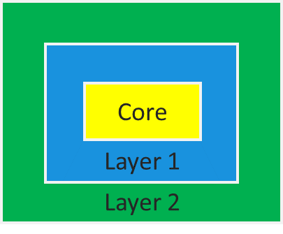
At the core layer you’ve got the core processing, memory, and communication interface elements. Layer 1 includes things like the application software and custom electronics, and then layer 2 includes the final packaging and integration. A more detailed visual would look something like:
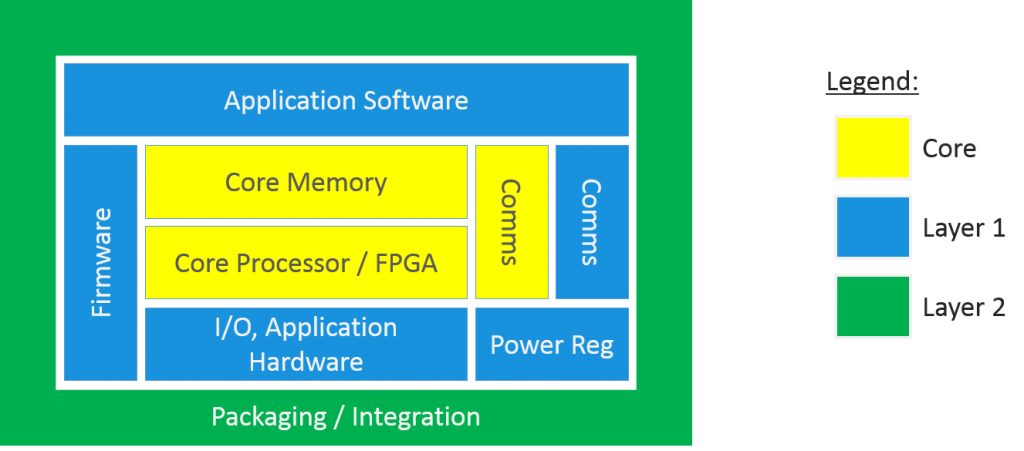
One of the biggest ways to reduce engineering development costs and risk is by utilizing existing hardware and software whenever possible.
Of course if some performance criteria can’t be met with something off-the-shelf, you have no choice but to utilize a custom component to satisfy that requirement. But whenever possible, you want to re-use what’s already been developed because that cost is likely being amortized, and existing components have already been validated.
The main potential candidates for re-use in a scenario like this are:
- Processor – absolutely. Many processors are architected for a variety of applications. In addition, if you can re-use many of the support components you put down onto a circuit board, then you get that re-use as well.
- Memory – absolutely. A similar story applies as for the processor.
- Communication Interfaces – in many cases, yes. While different applications do call for different communication interfaces, there are a handful of very popular interfaces for different applications, including Ethernet, USB, CAN, I2C, SPI, and RS-232/485/422.
- I/O Hardware – Many industrial applications follow the 80-20 rule whereby 80% of applications are satisfied by some common I/O, such as analog outputs (e.g. +/- 10 V or 4-20 mA) with a maximum of few 10s of kHz sampling rate, thermocouples, digital I/O (e.g. 3.3V or 5V), and some sensors needing excitation (e.g. bridge-style or IEPE). After a few projects, a set of I/O circuitry built for other projects can be reused for new projects.
- I/O Firmware – this is generally going to be tied pretty directly to your chosen I/O hardware, so depending on how much you can re-use your I/O hardware will mostly drive your ability to re-use your I/O firmware. On top of that, some serial interfaces are pretty prevalent, for example SPI, so that firmware has a high probability of re-use across different hardware.
- Power Regulation – this is very dependent on the various ICs that you need for your application, but there are certainly ways to increase re-use here.
- Application Software – much of this is going to be specific to your application, essentially by design. There still may be some potential areas for re-use with core functional blocks for things like PID loops and FFTs.
- Packaging – this is another area that will mostly be unique to your design.
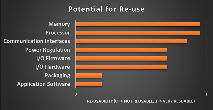
Based on this assessment, we’ll leave packaging and application software alone, since they aren’t usually the best candidates for re-use, and group the remaining items into two categories:
- Core Hardware – memory, processor, and some of the communication interface elements.
- I/O – we’re going to include I/O hardware and firmware in this category, as well as some additional communication interface elements. We’ll also lump power regulation into this category for now, even though it doesn’t quite fit, since our I/O (and core HW) will require power supply regulation.
Development Cost and Risk Reduction Category 1 – Core Hardware
The controller market offers a core hardware sub-assembly concept known as a System On Module (or SoM). There are several SoMs out there from various vendors. One of them is made by National Instruments. The NI SOM hardware (the NI sbRIO-9651 SOM) consists of the bare necessities to act as the core hardware element, including a processor, memory, some communication interface foundational elements, and an expansion connector to be able to connect your I/O to. The processor is a Xilinx Zynq SoC, which is a pretty awesome little chip, incorporating both an FPGA and a dual-core ARM-based processor in a single silicon package. Check out the Zynq-7000 devices here.
For more details on the NI SOM, check this out.
Development Cost and Risk Reduction Category 2 – I/O
Since you’re developing an industrial embedded machine, instrument, or piece of equipment, then chances are, you need to interface to something, so you’re going to need I/O. You might need analog inputs to monitor temperature, pressure, or vibration, or you may need 5V outputs or a serial interface to control a valve or actuator. Maybe you need GPS for position or timing information, or maybe you need to send data off to the cloud via Ethernet.
At Viewpoint we’ve taken some of the more common I/O and created modules out of them (some hardware, some firmware, and some both), and created a platform called VERDI to help with your I/O needs. Check out the VERDI modules here. If you need a module that we don’t have in our holster, we can design it for you.
Next Steps
Hopefully this article has provided a path for you to continue to make progress with your industrial embedded system. If you want to see if VERDI is a good fit for your application, request a demo. If you’re interested in more useful info on industrial embedded systems, check out our resources page.
LabVIEW FPGA – The Good, the Bad, and the Ugly

LabVIEW FPGA Programming – Pros and Cons
The good, the bad, and the ugly
F-P-G-A: to many software developers and integrators this is a four-letter word for a scary, dark place where monsters lurk
FPGA: to many developers and integrators this is a four-letter word for a scary, dark place where monsters lurk. I have been given an opportunity to learn FPGA, but not in the way that most FPGA developers use it. I am from the school of LabVIEW. This allowed me to add a whole new embedded tool (and sometimes a huge one) to my toolbox with very little brainpower investment. This has drastically increased the range of applications I can tackle. LabVIEW FPGA is a great tool, but not without its drawbacks, so let’s have a look at what some of the benefits, drawbacks, and just plain black holes there are.
LabVIEW FPGA Pros – the good
Reduced project completion time
While LabVIEW has a barrier to entry, like any other language, the bottom line is that one of the things that it excels at is being able to generate useful code to acquire and analyze real-world data quickly. This applies to LabVIEW FPGA too as it is just an extension of the base G language (LabVIEW graphical programming language). National Instruments (NI) does a wonderful job of abstracting hardware description language (HDL) from the G developer so one can write G code very similar to regular LabVIEW and have a working FPGA application in minutes.
Of course, a larger, more complex application still requires experience and good techniques to make a LABVIEW FPGA application meet size and timing requirements. This is still significantly less than most FPGA developers invest in learning HDL.
Simple simulation
LABVIEW FPGA has several simulation tools that allow you to quickly simulate the operation of the FPGA design. One very powerful tool is the ability to directly copy and paste LabVIEW FPGA code into a Windows context and execute the code with little or no changes. This will not preserve timing, but it is incredibly useful when you need to test the behavior of a state machine or other timing-independent code. There are also some useful techniques that can allow you to simulate timing if it is critical.
You get to leverage the existing NI ecosystem
This is another great benefit of LabVIEW FPGA. NI has a large (internal and external) ecosystem of code behind LabVIEW and that is extended to LabVIEW FPGA. Many libraries that are available for use in Windows are also available in LabVIEW FPGA.
There is also a large offering of common communication protocols that are available on the NI Tools Network, such as SPI, I2C, and RS-232 as well as some encryption algorithms. These allow a developer to implement one of these in a matter of minutes and are right at your fingertips via VI Package Manager.
For every I/O module they sell, NI also provides lots of example code that can be easily replicated and modified to your needs.
Large algorithms are much easier to understand in dataflow, and far quicker to implement in LV FPGA (an FFT is an example of this)
As an extension of the ecosystem discussion, some code is just much easier to understand in LabVIEW FPGA. Here is an example of a loop that implements an FFT.
Most developers, G or not, could look at this code and tell what it is doing. It does require opening a configuration dialog, but that is also very easy to follow.
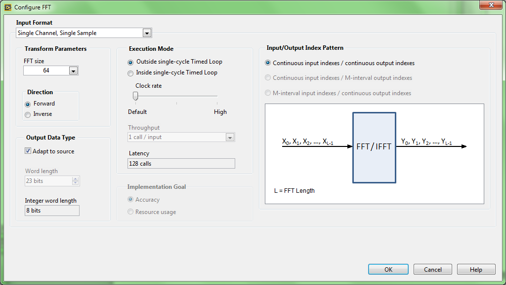
LabVIEW FPGA Cons – the bad
Notable overhead on all operations
Because LabVIEW FPGA is an abstraction of HDL, it adds a fair amount of overhead to the resource usage of any FPGA design. As FPGAs get larger, this becomes less of an issue, but it can still have a very real impact on time to completion. LabVIEW FPGA still uses the same Xilinx compilation tools (ISE and Vivado) that any other Xilinx FPGA developer uses, an equivalent design done in LabVIEW FPGA will take longer to compile every time. Once or twice an extra 10-20 minutes does not present a problem, but a complex design that must be compiled 20-30+ times at the additional cost of 30 minutes per compile can add up to days of compiler time. While most of this time can usually be offset by doing other work during the compile time, if you (or a whole team) are waiting for a compile to finish to begin testing the fix on hardware, it can be a significant cost. Most of the time, it is not worth worrying too much about, but it is something that everyone involved should be aware of.
The other problem that this causes is that it allows you to get less done in a LabVIEW FPGA design vs. an equivalent HDL design when trying to pack more in to a design.
An example of this overhead would be in the implementation of a state machine, which is very common in LabVIEW code. A state machine in HDL can be recognized by the compiler and synthesized to a very specific set of flip-flops. In LabVIEW, a state machine is represented by a loop with a case structure that is evaluating an enum. The compiler is not going to recognize this as a state machine, but rather a collection of higher level objects that will use more resources in synthesis.
Dataflow might be challenging for those coming from a non-dataflow world
Of course, being a LabVIEW developer, I think in dataflow. That may not be so easy for those coming from the text-based world. If your code needs to be understood by a team of non-dataflow developers LabVIEW FPGA may (or may not) be harder for them to read than HDL.
You are a level removed from the Xilinx tools
Again, thinking of LabVIEW FPGA as an abstraction, NI does not provide nearly as much control of the FPGA design as when you are using the Xilinx tools directly. This means that many of the knobs that you might turn to constrain or optimize a design are just simply not available in LabVIEW FPGA. For 95% of LabVIEW FPGA developers this will not be a problem, but when you need those tools, it can be a significant hurdle. Notice that I used the word hurdle. In none of our designs was this a show-stopper, but in a couple of cases, we needed to engage NI applications engineers directly to help us solve layout issues.
Difficult to source control
All good programmers worth their salt use source control to protect and version their code. LabVIEW source files (VIs) are proprietary and binary and thus more difficult to source control. Viewpoint has created an add-on tool for LabVIEW that allows you to use SVN right in the LabVIEW IDE, but distributed version control (DVCS) tools like Git or Hg are very difficult to use with LabVIEW.
Some complex applications still require writing HDL
In some cases, you can’t get away without writing some amount of HDL. Viewpoint has completed some applications where the customer needed a custom physical connector or a specific LVDS driver on a FlexRIO Adapter Module (FAM), a unique Aurora configuration, or some combination of those. These specialized cases require the ability to write HDL for the FAM Component-Level IP (CLIP), which creates the interface between LabVIEW FPGA and the physical interface, or for the link layer protocol. It helps to have experienced developers in both LabVIEW FPGA and HDL.
The Ugly
Can only view within the LabVIEW tools
One major drawback to working with NI tools is that the file format is proprietary and can only be viewed and edited with LabVIEW, which has a non-negligible entry price in the thousands of dollars to start working with LabVIEW FPGA.
Next Steps
We’ve got over 700 LabVIEW FPGA projects under our belt. If you’d like to chat about your LabVIEW FPGA needs, you can reach out to chat here.
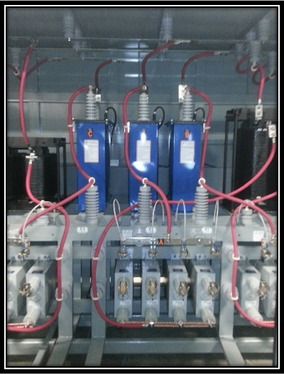
Keeping the Electrical Grid Healthy with VAR Compensation

Keeping the Electrical Grid Healthy with VAR Compensation
While certainly an issue for the massive U.S. power grid, power supply is also a concern for smaller scale voltage systems
The U.S. power grid is a large electrical circuit that, although has some amount of isolation between loads, is interconnected at drop points. This interconnection is very important, as power must be monitored and sustained to prevent failure or outage.
While certainly an issue for the massive U.S. power grid, power supply is also a concern for smaller scale voltage systems.
T-Star has significant domain expertise in stabilizing medium voltage power systems. When the team needed a well-supported intelligent device for their new generation Static VAR Compensator (SVC), they contacted Viewpoint Systems based on our expertise in measurement and control systems.
An SVC is a set of electrical devices that is used to regulate grid voltage. An SVC is generally worth considering in scenarios where large electric motors are being utilized (e.g. mills, recycling plants, mines). Problems such as voltage sag, voltage flicker, and current harmonics can cause reduced motor torque, lights to flicker, and equipment damage.
T-Star and Viewpoint Systems worked together to create a dynamic quality power system that can be remotely monitored and diagnosed through real-time data. The power system consists of hardware and software from Viewpoint Systems and National Instruments, including LabVIEW system design software and an NI CompactRIO controller, which is well suited to perform multi-channel precision timing and high speed logging in dirty, industrial environments.
A diagram of the T-Star system and solution benefits can be found here.
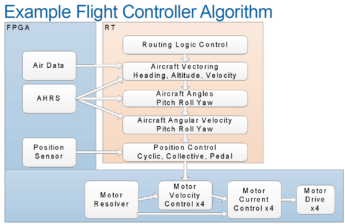
Industrial Embedded – Article – Creating a Real-Time Helicopter Autopilot

Industrial Embedded – Creating a Real-Time Helicopter Autopilot
We congratulate both our client and our engineers for making this very cool project a huge success
We had fantastic attendance at our NIWeek presentation titled ‘cRIO Takes Flight – Creating a Helicopter Autopilot’. This presentation covered our development of a cRIO-based embedded controller that could control the orientation and position of an experimental helicopter — an actual autopilot!
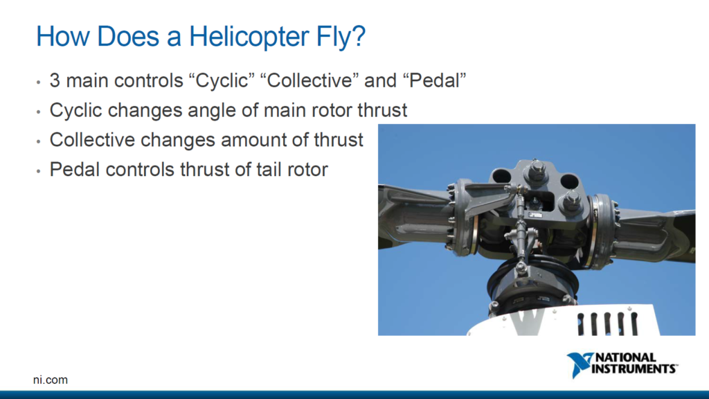
The cRIO was connected to several of the helicopter sensors, including GPS, and flight-control actuators which enabled the real-time application control loops to keep the helicopter on a pre-defined flight path.
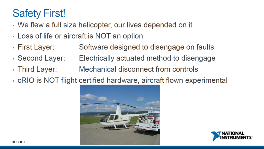
For safety reasons, the pilot had complete manual override capability and at any time could take command of the machine. However, with the rapid development and deployment tools offered by LabVIEW coupled with the flexible COTS cSeries modules HW, the cRIO embedded development effort was less than 3 weeks. Furthermore, initial autopilot flight goals were met in 2 days.
We congratulate both our client and our engineers for making this very cool project a huge success! You can check out the complete presentation here: Creating a Helicopter Autopilot. If you want more useful info on industrial embedded systems, check out our resources page here.
How to Remotely Monitor Electrical Power Signals
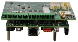
How to Remotely Monitor Electrical Power Signals
These local power sources are typically alternative, such as solar and wind, which have intermittent power levels
As Smart Grid investment grows, two important premises for Smart Grid design are:
- Access to local power sources
- An understanding of loads and disturbances on the grid at various locations
These local power sources are typically alternative, such as solar and wind, which have intermittent power levels.
Since the levels fluctuate, an important feature of proper Smart Grid operation is handling these erratic supplies. Optimal understanding of these disturbances and load changes increasingly requires measurements on individual AC power cycles.
Local power analysis systems typically have constraints in equipment cost, size, and power usage, balanced against the need for simultaneous sampling front-end circuitry and back-end custom data processing algorithms. Furthermore, many of these systems are presently deployed as prototypes or short-run productions, requiring a combination of off-the-shelf and custom-designed components.
Viewpoint Systems recently worked with a designer and manufacturer of leading-edge electrical power monitoring equipment to provide access to simultaneously sampled signals from the 3-phase and neutral lines of an AC power source.
Using a custom RIO Mezzanine card (RMC) designed and built for the National Instruments SingleBoardRIO platform, Viewpoint Systems delivered a powerful, cost-effective, and configurable solution for AC power signals measurement.
Power Line Data Acquisition sbRIO RMC Module with GPS Timing
Furthermore, through the GPS component on the RMC, measurement units can be placed at dispersed locations while still providing adequate synchronization of acquired waveforms. This aids in localizing and understanding disturbances in power transmission and distribution, irrespective of any specific application.
Read the full case study to learn more about the application and view full specifications of Viewpoint Systems’ remote monitoring system for electrical power. If you have an embedded monitoring application that you’d like help with, you can reach out to chat here. If you’d like to learn more about our circuit board design capabilities, go here.
How Much Does it Cost to Design an Embedded Controller For Industrial Equipment?
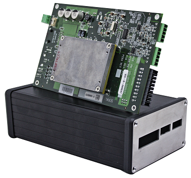
How Much Does it Cost to Design an Embedded Controller For Industrial Equipment?
This article is geared toward companies in the industrial space (vs consumer), that manufacture systems or sub-systems (machines, equipment) that are generally reasonably expensive, and have lower production volumes (~10 – 1,000 units per year).
The emphasis of this article is on the prototyping of the embedded controller. When I say “embedded controller” in this context, it doesn’t mean that it actually has to control anything, but it will most likely have outputs. It could simply be monitoring signals to convey useful information to another piece of the system or system of systems.
What’s out of scope for this discussion?
- Manufacturing costs: while production volume should absolutely be taken into consideration for off-the-shelf vs custom component selection, I won’t focus on the manufacturing end of the product development process; rather I’ll focus on the prototype development costs. Of course, designing with production in mind (not just volumes, but DFA& DFM as applicable as well) is still critical.
- The post-production maintenance, obsolescence, and customer support aspects are not part of this discussion either.
- The front end research: in other words, an idea exists, but hasn’t been prototyped or proven out yet, or if it has, it’s been a lab-equipment-based proof-of-concept hack job.
Example Embedded Controller Costs:
 I’m going to throw the caution flag here. Examples are tricky. We like them because they are very tangible. They’re also very dangerous because they are so situational and make many assumptions. Your particular scenario may vary significantly, but we’ve got to start somewhere, right? It’s worth noting that the labor costs below are fully loaded (salary, benefits, overhead, etc). So with those caveats, I offer you the following two examples of embedded controller design costs.
Example 1 (circa 2017): Relatively Straightforward Embedded Controller
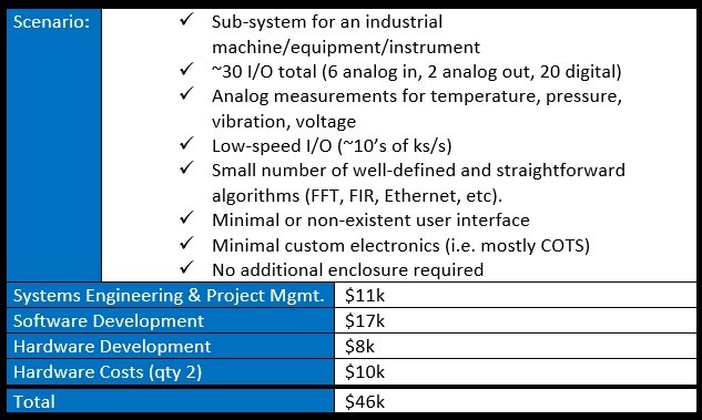
Example 2 (circa 2017): Relatively Complex Embedded Controller
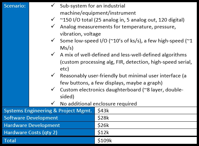
Key Cost Drivers:
- Re-use libraries: these include both hardware components (e.g. a particular signal conditioning sub-circuit) and software components (e.g. a particular communication protocol interface).
- Off-the-shelf hardware availability: generally when a component can be purchased (that meets the designs requirements), it will be cheaper to buy than to design from scratch.
Cost Breakdown:
Estimates for engineering costs are challenging. The main reason is because something is being created from nothing, and there are a lot of components (software and hardware) that have to work together in harmony (protocols, algorithms, physical interfaces, power consumption, heat dissipation) in order for the embedded controller to perform as desired.
Much of the ability to generate reasonable cost estimates comes from leveraging past experience solving similar problems. Being able to recognize the differences in hardware and software platforms and requirements, allows seasoned engineers to quickly estimate the amount of work required.
The other cost estimation technique often utilized is bottom-up cost estimation. This is where you start from extremely low-level components that can be estimated, and sum the parts to come up with a final tally. When I say low-level components, I mean down to the level of something like:
- An algorithm, like an FFT, or maybe even lower level like a butterfly element
- GUI elements, like a plotting function
- A circuit board sub-circuit, like a particular SMPS
Combining past experience with bottom-up cost estimation is pretty typical in the engineering world.
The biggest challenge/unknown from a costing standpoint is generally estimation of integration and debug of the prototype. This is where the various components that were developed and simulated all have to start working together.
The costs that people don’t like to think about:
Embedded designers are more apt to want to focus on the creation aspect of the core design (e.g. coding on the software/firmware side, and circuit design on the hardware side), and less likely to want to pay as much attention to costs associated with tasks such as:
- Requirements – developing and managing requirements isn’t free, but it can cost you even more by not paying attention to them.
- Project management – hardcore developers often hate project management, often seeing it as superfluous. On the smallest of projects, project management can be handled individually. Otherwise, at a minimum, it’s a necessary evil, and if done well, it can make the development team’s life better by helping them not get overloaded, helping clear roadblocks, and providing clear goals.
- Risk mitigation – If nothing ever goes wrong with any of your projects, I’d be grateful if you’d get in touch with me and explain your magic.
- Documentation – This can get out of hand for sure. Keep it to a minimum. The three best reasons to document in my mind are: (1) to help you design in the first place (2) to help teach someone else whatever they need to know (3) to help you remember what you did a year or more later. If none of these criteria are met, you may want to second-guess your effort.
- Integration – Integration/interfacing of things is becoming more and more prevalent. Just always remember that whenever you create a new component, you need to interface with it somehow, and you should allocate time for this.
- Debugging – I wrote an article on this topic to help with the debugging process.
- Hardware re-spins – It is possible to design a custom circuit board well enough on the first shot that a re-spin is not needed;it’s just highly unlikely. I wouldn’t recommend planning for it.
- Certifications – You may not require certification for your prototype, but you probably want to start thinking about it so you don’t design yourself into a corner.
Next Steps:
Presumably if you’ve made it to this point in the article, you’re likely either:
- Overloaded and just need some additional resources to get the job done.
- Relatively new to the embedded world and are considering pulling in some outside resources to help.
- Curious about alternative ways of doing things.
If you’re interested in scoping the cost of an embedded controller for your application, you can reach out to us here. If you’re interested in understanding how we can help, go here. If you want to see the sorts of requirements you should be thinking about, go here. If you’d like to get a feel for the engineering labor costs to develop the prototype embedded controller for scenarios that are able to utilize off-the-shelf hardware, see our engineering prototype cost calculator.
How is Embedded System Design Different For Small Companies?

How is Industrial Embedded System Design Different For Small Companies?
The main differences between embedded design for small companies versus large can be grouped into four main categories
Background:
As electronic sensing and processing power increases, more and more companies are coming out with great ideas that are functionally and financially feasible. The problem shifts more from “if we can implement these ideas” to “how we can implement these ideas.” Large companies have had the resources for years, and in some cases decades, to embed electronic intelligence into their products. The threshold for feasibility is decreasing, making it easier for smaller companies to enter the market. This is mainly due to:
- Lower cost per processing operation
- Lower cost per bit of information stored
- Lower cost per bit of information communicated
- Continued miniaturization of electronics
- Lower power consumption per processing operation
To be clear, when I say “small companies,” I mean those with fewer than 100 employees. I’m talking about companies in the industrial space (v.s. consumer), that manufacture sub-systems or systems that are generally more expensive (~$1,000s – $100,000s per unit), and have a relatively low production volume (10s to 100s of units per year).
The differences between embedded design for small and large companies matter because:
- They can help small companies become aware of potential pitfalls before they get in too deep.
- They can level the playing field for small companies.
Differences:
The main differences between embedded design for small companies versus large companies can be grouped into four main categories: capital, people, process, and organization.

Capital
Smaller companies generally have less working capital. They may have limited funds for:
- Development and debugging tools (e.g. Xilinx Vivado, Intel Quartus Prime, OrCAD, Eclipse) for doing schematic capture, board layout, simulations, and software/firmware development can range from free to sometimes costing thousands to tens of thousands of dollars to purchase, with an additional annual maintenance cost for each tool.
- Lab equipment, such as logic analyzers and oscilloscopes (e.g. Tektronix Logic Analyzers, Tektronix Oscilloscopes), can cost thousands to several tens of thousands of dollars per piece of equipment. There are less expensive routes for initial cost, but keep in mind that generally speaking (in steady state), you get what you pay for, so a piece of equipment that has a lower purchase price may have lower performance (so make sure you understand your needs), lower reliability, or take more time to use. This last point is one that people often don’t weigh strongly enough in their decision-making. Time is often one of the engineering community’s most valuable resources. Another option is renting equipment. This comes with the obvious benefit of lower cost, but the risk is the possibility of out-of-calibration or misuse from the previous renter.
- Lab space – make sure to have enough room for development hardware, lab equipment, and computers (as well as enough power to handle all this gear). In addition, ESD is an important aspect of dealing with sensitive electronic components (check out ANSI/ESD standards). Components can be fried immediately, or sometimes worse, set up for a latent failure.
People
- Team sizes are often much smaller. Whereas a larger company may have several people that only do embedded software or only do embedded hardware, a smaller company might have an entire product development team that is just a handful of people, limiting the expertise to what is truly core for the company. An embedded developer in a small company might wear many hats, or there may not be an embedded developer at all and the company may rely on external resources to augment the team.
- Focus: smaller companies often rely on particular domain expertise. This is the core of why they (the companies) exist, and may be what keeps them afloat. They may be scientists with a really cool new idea, or they may be a more mechanically oriented company that builds electro-mechanical machines or equipment. Because of this, they may not have the ability or inclination to become experts with embedded systems. The algorithm may be very important to the smaller company, but the way that it is implemented may not be. Having some capability to sense a particular property or measure a particular parameter may be very relevant, but how it gets done may not be.
Organization
- Agility: Small companies are able to respond/react to market feedback faster. This Tech Crunch article discusses some ways in which bigger companies are trying to behave more like smaller companies: How Big Companies Are Becoming Entrepreneurial
- Small teams feel ripples from small events more than a larger company would. For example, if someone gets pulled off onto another project or leaves the company, a larger company may have the resources to plug in a new person, but a smaller company may not have this ability. Even losing a 25 percent of a full-time person on a small team that can’t be backfilled can be detrimental to a project.
- Small companies generally have less red tape to go through in order to get approvals faster and try things outside the scope of what is considered normal. For example, if a new embedded system has been released to a customer, and that customer needs a feature that isn’t available in the release, the smaller company will likely have a much easier time getting approval to add the new feature if it makes sense than if the same request is made to a larger company.
Process
- A large company may have a very well-defined, rigorous process for development, such as various design review gates, release processes, and documentation, whereas smaller companies may just focus on getting stuff done. The benefit is that the small company may get through development faster, however the risk is that if there is a flaw in the design, or bugs aren’t caught, it gets more and more expensive to fix later on (check this out: NASA – Error Cost Escalation Through the Project Life Cycle ; even though it’s old and based on developing systems that are very complex, the general trend likely holds, although the multipliers likely go down significantly).
- Smaller companies are less likely to develop a rigorous set of requirements and specifications, and the embedded developer will likely be involved throughout the project, whereas in a larger company they may not get involved until well into the project, where they are handed a set of derived requirements for their portion of the design.
- Larger companies may be more mature from a configuration management standpoint, including source code control, release process and version control.
So What Now?
Hopefully this article improved or solidified your mental model in some way and you feel more confident to take the next steps either on your own or engaging with an external company. If you’d like to chat about your embedded needs, you can reach out to us here. If you’d like to learn more about how we can help with your industrial embedded needs, see here. Or, if you’d like more information on industrial embedded systems, check out our resources page.
HDL FPGA Development – The Good, the Bad, and the Ugly

HDL FPGA Development –
The Good, the Bad, and the Ugly
Let’s talk about where FPGAs are today, where they were just a few years ago, and some pain points that still exist
Intro
Each year the various journals and publishers of embedded systems design material are seeing more and more talk of field-programmable gate arrays (FPGAs). FPGA technology is often talked about as one of the most powerful, but also one of the most frustrating parts of the embedded designer’s arsenal. With each generation of FPGA technology being faster, having smaller geometry and lower power, and with more logic gates, all for less money per operation, the possibilities seem endless. However, with great power (and re-configurability) comes, at least with FPGAs, some serious learning curves and frustrating days (weeks) at the office. Let’s talk about where FPGAs are today, where they were just a few years ago, and some pain points that still exist.
The Good
Large, Reconfigurable, Sea of Logic Gates
FPGA technology allows a designer to implement nearly any algorithm and/or control that she or he likes. Modern-day FPGA fabric is made up of tens to hundreds of thousands of logic gates and flip flops that can be combined together to implement everything from a button denounce circuit to an x16 PCIe gen-3 host controller. Using FPGAs within your design gives you the near infinite freedom to implement whatever functionality you need.
Abstraction Layers
It sounds terrifying to design a system using 74LS logic ICs, and the folks who were working on the first FPGAs had to do nearly that. Luckily today we don’t have to think on such a low level. There are languages, called hardware description languages (HDLs), which help designers describe their design to a synthesizer that then creates net lists of logic equations and registers. Additionally, there is a wide range of higher-level abstraction technologies and languages. Xilinx provides a tool called Vivado HLS (HLS stands for high-level synthesis) that allows a designer to write C, C++, or System C and have it generate HDL in the form of VHDL or Verilog. Here at Viewpoint Systems we often use a technology called LabVIEW FPGA, which allows you to describe FPGA designs using a graphical programming environment that leverages dataflow paradigms.
Resources and Ecosystem
Commercially available FPGAs have been around since the mid-1980s. That’s a long time for a technology, and its ecosystem, to mature. There are LOTS of resources available for everything from understanding how the silicon is laid out, to how the synthesizer generates net lists, to the best methods to write HDL to generate the logic structures you’re looking for. You can go onto Amazon and search FPGA and find hundreds of available books. If you google FPGA, you can find tens of thousands of answered questions available for reference. Because HDL is text-based, these question and answers are indexed by search engines, making finding information simple and fast.
Also, in the last several years more resources have come out about the higher-level synthesis tools such as Vivado HLS, Calypto, and LabVIEW FPGA.
Speed and Size
Modern FPGAs can run really fast – like hundreds of megahertz fast. You may be thinking: “But Tim, my Intel processor runs at gigahertz fast!” That is true! However, your Intel processor is a “general-purpose processing unit” – it does a large number of things pretty well, not a small number of things really well. FPGAs allow you to write massively parallel implementations of algorithms producing throughputs that can be 10x, 100x, or 1000x higher than any CPU on the market today.
Although high-level abstraction is great for faster time-to-market (TTM), you simply will never be able to get your design to run as fast, or be as small as writing the code by hand in a traditional HDL such as VHDL or Verilog. The abstraction languages and technologies can be great for quickly putting something together; however, the inevitable overhead will always make your design larger, and thus slower (lower maximum clock speed).
The Bad
Learning Curves
As anyone working with FPGAs on a regular basis will tell you, the learning curve is pretty steep. This rather unfortunate aspect of working with FPGAs means that someone looking to enter the world of FPGA design needs to either undergo extensive training in the work place (which can be quite costly at up to $1500/class), or engage in intense self-motivated learning.
“It Works In Simulation”
HDLs inherently suffer from needing to be written and tested on a different platform than they will be “run” on. In the case of VHDL, it is very easy to write VHDL code that works perfectly fine in simulation but would never work in hardware (loaded into the FPGA). This includes trying to do too much between clock cycles (like trying to perform dozens or hundreds of multiply-and-accumulate (MAC) operations for a finite impulse response (FIR) filter).
The flow of writing and validating HDL is usually something like this:
- Identify the inputs and outputs of the entity
- Identify any algorithms needed to be implemented within the entity
- Produce block diagrams for the different parts of the design
- If applicable, draw out the state machine states and transition diagram
- Write code
- Check syntax
- Simulate
- Verify operation against requirements and datasheets
- Check if it works
- 1. If no, go back to #5
- Load into hardware to test
- Check if it works
- 1. If no, go back to #5
- Design Review(s)
The problem with this flow is you can get stuck in a vicious cycle of 11a -> 5 over and over until you’ve driven yourself mad. A very big part of being a proficient FPGA designer and programmer is knowing what the code you are writing is actually creating. This means consistently checking the schematic that is generated by your code, and keeping your code as small as possible (this also makes testing easier!).
Additionally, it’s easy to write code that produce massive amounts of logic with a single line. Here is an example:
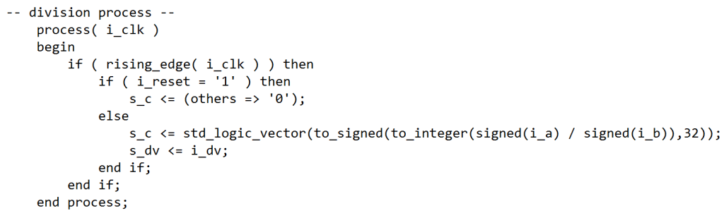
The above code, generates this schematic:
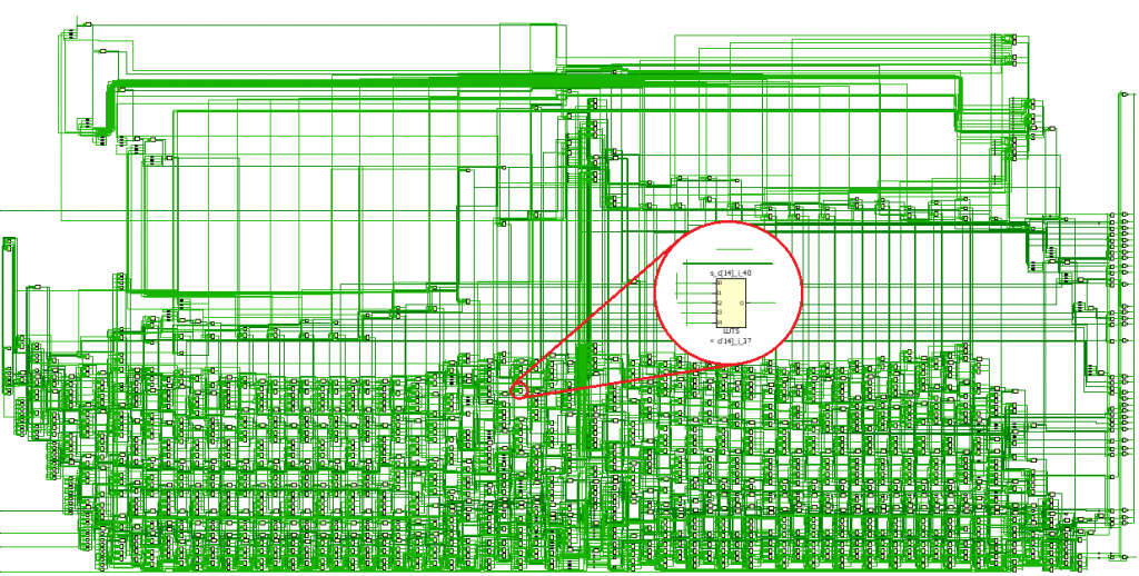
Vivado created a divider, as requested, but it took almost 1800 cells to do it. Meeting timing on this operation may prove to be very difficult, especially if it is a part of other logic operations that have to happen that clock cycle.
The Ugly
The Tools Aren’t Great
There is nothing quite like the frustration that comes from software tools that don’t do what you expect them to, or produce inconsistent results. Although commercial FPGAs have been around for quite some time, some aspects of the software ecosystems still are lacking. With the latest version of the Xilinx tools, Vivado, the industry has seen a large jump in functionality and features. However, since this tool is brand new and a near-complete rewrite of their legacy tools. It has its own set of challenges and bugs. Altera, the number two FPGA manufacturer, is still working with the same software package that they have been using for over a decade. To put that in perspective, that’s like running Windows ME today thinking that it was appropriate.
Debugging Timing Violations
Timing. Ugh. I’ve probably spent the most time being frustrated with FPGA design when it comes to some rough little bit of a netlist that just refuses to meet timing, no matter what I do to it. These little “show stoppers” come about all of the time. And the best way to squash them is simply with experience – there really isn’t much else that a designer can do. Xilinx has their UltraFast Design Methodology guide, and Altera copious amounts of documentation for “best practices,” but really when it comes down to it, it’s all about writing good, small, synthesizable HDL code. But no matter what, you’re going to find yourself in a situation where you need to instantiate 32 of something, and timing is going to be a nightmare. If you’d like to chat about your embedded needs, you can reach out to us here. Or, if you’d like more information on industrial embedded systems, check out our resources page.
Next Steps
If you’d like to chat about your industrial embedded needs, you can reach out to us here. Also, here’s some additional resources to help you on your journey:
- Custom Automated Test System Buyers Guide
- LabVIEW FPGA: The Good, the Bad, and the Ugly
- Outsourcing Industrial Embedded System Development Guide
- Need LabVIEW FPGA programming help? | LabVIEW FPGA Developers
- LabVIEW Industrial Automation Guide
- Industrial Embedded Design Resources – White Papers, Case Studies, Articles
- Automated Test System Resources – Webinars, White Papers, Case Studies, Articles
Gleason Reduces Gear Manufacturing Time by 30% Using Viewpoint Systems

Gleason Reduces Gear Manufacturing Time by 30% Using Viewpoint Systems
Viewpoint and Gleason created a patent-pending system that produces higher quality gears in 30 percent less time
Bevel and cylindrical gears can be found virtually everywhere – from automobiles and airplanes to trucks and tractors, and from giant wind turbines that can power a thousand homes to lawn mowers and power tools.
Gear tooth surfaces and spacing are never perfectly machined, and consequently, noise and vibration are often present in applications where the gears are later used. Gears, after the typical heat treatment process, are commonly lapped or ground to smooth the gear teeth surfaces and improve operational characteristics. This should reduce the surface and tooth spacing deviations that produce noisy gear sets.
The Gleason Corporation and The Gleason Works, a global gears solution provider, enlisted Viewpoint Systems to help create a torque-controlled lapping solution with responsive, real-time feedback to create better quality gears and reduce cycle time for its gear lapping machines.
The result – Viewpoint and Gleason created a patent-pending system that produces higher quality gears in 30 percent less time. The new system, founded on embedded control and dynamic real-time process monitoring technologies, creates the unprecedented ability to improve gearset quality during lapping, and to do so at higher speeds.
Download the case study to learn how Viewpoint Systems developed the solution using NI LabVIEW and NI CompactRIO hardware.
Contact Viewpoint to discuss your application needs.
Getting Data In and Out of the NI-9651 System on Module (SoM)
Getting Data In and Out of the NI-9651 System on Module (SoM)
National Instruments released their latest technology in their line of single-board reconfigurable input/output (sbRIO) products: the NI-9651. The NI-9651 System on Module ( SoM ) is unlike any RIO product that NI has released, and is by far the most powerful.
The NI-9651 takes the Xilinx Zynq-7020 System on Chip ( SoC ) and pairs it with 512MB of memory and 1GB of non-volatile flash, and brings out over 160 I/O to two connectors. The SoM also has a feature that other sbRIO products haven’t had: it runs the Linux kernel.
SoM vs sbRIO
Previous generations of the sbRIO products from NI have included digital and analog inputs, as well as a large amount of the support electronics needed to run the module. I/O such as UART, Ethernet, and USB were included on the module. The NI-9651 is different in that it needs quite a bit more support circuitry to operate. The SoM does not have any connections to it other than two Samtec connectors on the bottom of it; thus, the carrier circuit board that it is mated with must include support circuitry such as:
- Power conditioning and voltage generation
- The SoM needs a number of different voltages to work correctly.
- IO connectors
- Ethernet, USB, CAN and UART are all supported by the SoM; however, the various circuits needed to take advantage of these I/O are not included and must be supplied.
- Analog-to-digital converter to get analog signals into LabVIEW
- You may also need analog front-end circuitry to condition the signal.
- Digital input signal conditioning
- Even digital inputs usually need to be conditioned in some way, if anything over/under voltage protection should be used.
The Socketed Component-Level Intellectual Property (CLIP)
Once the SoM is in its carrier board or a custom circuit board, the various I/O needed by the system need to be identified and those circuits connected or created. Once that is done, the signals from those circuits and devices must be brought into LabVIEW FPGA and possibly LabVIEW RT. The bridge between the outside world and LabVIEW FPGA is the Socketed CLIP.
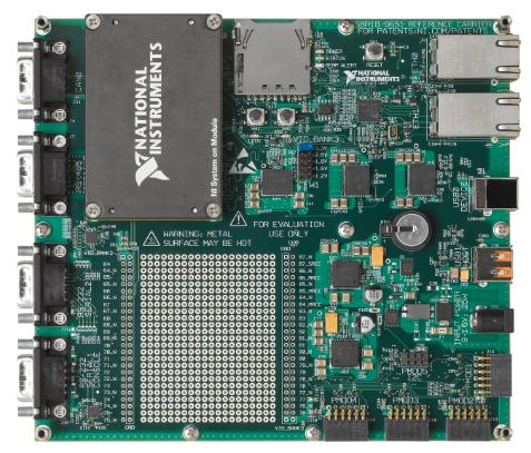
Reference carrier board for NI-9651
The Socketed CLIP is written in a hardware description language (HDL), usually VHDL or Verilog. These languages are inferred languages. The interpreted language tells a Xilinx synthesizer information about the logic that it needs to accomplish a task, and then the synthesizer produces the technology-specific configuration to implement the solutions to those tasks. We use VHDL here, as it is very verbose and strongly typed, and thus results in clear, concise code.
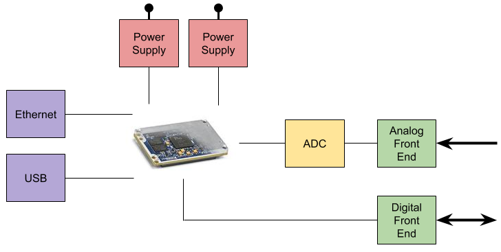
Example SoM Block Diagram
Within the Socketed CLIP usually exists the logic and state machines to initialize the various circuits and components that exist on the circuit board attached to the SoM. The Socketed CLIP may also include translations between I/O types such as LVDS and single-ended signals. Additionally, any device-specific IO features, such as delays or serializers, must be implemented in the Socketed CLIP, since LabVIEW FPGA does not know how to work with those technologies.
Finally, once the CLIP has been written and all of the signals have been converted to work with LabVIEW FPGA, the Socketed CLIP can be instantiated into the design, and its I/O can be accessed via LabVIEW FPGA via FPGA I/O node blocks.
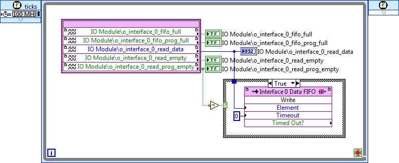
Example LabVIEW FPGA code, where data is moving from the CLIP to a target-to-host FIFO.
LabVIEW FPGA is an extremely powerful tool for a LabVIEW programmer to have in their tool belt. One struggle, however, can come when the need arises to interface with a technology that LabVIEW FPGA does not speak natively. This is where using the SoM can be advantageous, and leveraging the power of a traditional HDL such as VHDL can help. The SoM has many great uses. Adding good analog and digital circuit design and a proficiency in HDL can elevate the usefulness of the SoM by quite a bit. If you’re considering utilizing the NI SOM, start here first. Or, if you’d like more information on industrial embedded systems, check out our resources page.
Designing An Industrial Embedded Controller – Important Costs To Consider – Part 2

Designing An Industrial Embedded Controller – Important Costs To Consider – Part 2
The emphasis of this article is on the prototyping of the embedded controller
This article is a continuation of part 1. If you’ve not already read part 1, please start here. As a re-cap, last time we covered the following costs:
- Requirements
- Project management
- Risk mitigation
- Documentation
The emphasis of this article is on the prototyping of the embedded controller.

Let’s jump right back into it:
Cost 5: Interfacing –
Just always remember that whenever you create a new component, you need to interface with it somehow, and you should allocate time and effort for this. Consider low coupling and open standards whenever feasible.
Here’s why you should care: Interfacing with other components, sub-systems, or systems is becoming more and more prevalent. It offers benefits along the lines of the whole being greater than the sum of the parts. We’ve got a webcast on interfacing to help.
Cost 6: Debugging –
Debugging often has negative connotations associated with it because engineers might think that it means they messed something up that they shouldn’t have, and now they have to fix it in a hurry. This is the wrong way to think about it. While it does generally mean that something was coded, designed, or interfaced incorrectly, these imperfections should be expected.
Here’s why you should care: debugging doesn’t have to be a stressful thing if you are prepared. It can actually be one of the more fun parts of the development process. It’s both a puzzle to solve and a learning experience. I wrote an article to help with the debugging process.
Cost 7: Hardware re-spins –
It is possible to design a custom circuit board well enough on the first shot that a re-spin is not needed; it’s just highly unlikely. I wouldn’t recommend planning for it.
Here’s why you should care: if you plan for a re-spin (or maybe even more depending on your scenario) and you don’t need it, you come out ahead of the game from a cost and schedule standpoint. If you don’t plan on it and you need it, life gets very unhappy very quickly.
Cost 8: Employee performance variation –
People don’t like to talk about this, but not everyone works at the same speed, and sometimes at quite sizable deltas. If you take the average engineer at a given level of skill, I’d say most people work within about +-25%’ish of that range, but I’ve seen people that I’d say performed as much as +-50% faster/slower than that average.
Here’s why you should care: If the project team is large enough (say with ~10 people or more), these variations tend to average themselves out, but with small teams of 2-3 people, the variations can make or break a project. I’d recommend either being aware of who will be on the project team in the planning phase, or if that’s not possible, be conservative with your estimates.
Cost 9: People/team issues –
Many engineers thrive off of solving technical and analytical problems, and are more apt to view people-oriented problems as superfluous. The challenge here is that for problems of any significant complexity, people need to organize into teams, which creates a necessary new class of problems to address.
Here’s why you should care: Friction between team members that don’t get along can create project inefficiencies (generally stemming from a lack of communication) or can even de-rail high-stress moments such as demonstrations.
So what now?
If you’d like more useful info on industrial embedded systems, check out our resources page. If you’d like help scoping the cost of your industrial embedded controller, you can reach out to us here. If you don’t have the time or the manpower to develop your own embedded solution, check out VERDI.
Designing An Industrial Embedded Controller – Important Costs To Consider – Part 1
Designing An Industrial Embedded Controller – Important Costs To Consider – Part 1
Estimates for engineering development costs are challenging, and I mean really challenging
The emphasis of this article is on the prototyping of the industrial embedded controller.
When I say “embedded controller” in this context, it doesn’t mean that it actually has to control anything (it could, but isn’t required), but it will most likely have outputs. It could simply be monitoring signals to convey useful information to another piece of the system or system of systems.
This article is geared toward companies in the industrial world (vs consumer), that manufacture systems or sub-systems (machines, equipment) that are generally on the more expensive side (~$4,000 – $200,000 per system), and have lower production volume (10 – 1,000 units per year).
What is out of scope for this discussion?
- The front end research: in other words, an idea already exists, but it hasn’t been prototyped or proven out yet, or if it has, it’s been a lab-equipment-based proof-of-concept hack job.
- Manufacturing costs: while production volume should absolutely be taken into consideration for off-the-shelf vs custom component selection, I won’t focus on the manufacturing end of the product development process; rather I’ll focus on the development costs. Of course, designing with production in mind (not just volumes, but DFA& DFM as well) is still critical.
- The post-production maintenance, obsolescence, and customer support aspects are not part of this discussion.
The industrial embedded development costs that people don’t like to think about:
Estimates for engineering development costs are challenging, and I mean really challenging. The main reason is because something is being created from nothing, and there are a lot of components (software and hardware) that have to work together in harmony (protocols, algorithms, physical interfaces, power consumption, heat dissipation) in order for the embedded controller to perform as desired.
I think the majority of costs that engineers don’t like to think about are areas that are generally considered less fun, but that doesn’t make them any less valuable.
Embedded designers are more apt to want to focus on the creation aspect of the core design (e.g. coding on the software/firmware side, and circuit design on the hardware side), and less likely to want to pay as much attention to costs associated with tasks such as these 9 that I’ve identified below.
Cost 1: Requirements –
Many of the more formal methods for requirements generation and management may be overkill for some industries, and sometimes people get out of hand with requirements, but that’s not a good reason not to do anything at all. Consider developing a minimum set of requirements for your scenario.
Here’s why you should care: Requirements are the core of communicating what your industrial embedded system will become. Often the objective with requirements is getting one person to convey and organize information that’s in their head, with others. Developing and managing requirements isn’t free, but it can cost you even more by not paying attention to them. Not having requirements could create the need for a board re-spin, or could cause processor overloading. Requirements ultimately transform into what you design and test against. What you test against ultimately is what you judge success or failure against.
Cost 2: Project management –
Hardcore developers often hate project management, seeing it as superfluous. On the smallest of projects, project management can be handled individually. Otherwise, at a minimum, it’s a necessary evil.
Here’s why you should care: Project management can make the development team’s life better by helping you:
- not get overloaded
- clear roadblocks
- by providing clear goals.
Cost 3: Risk mitigation –
If nothing ever goes wrong with any of your projects, I’d be grateful if you’d get in touch with me and explain your magic. Otherwise, you should understand the likelihood and severity of your main risk items.
Here’s why you should care: Understanding your main risk items can help you come up with backup plans if a risk item occurs, and at a minimum, can be used as a tool to set expectations with the team, management, and your customer.
Cost 4: Documentation –
There are a few people out there that enjoy documenting. For the rest of us that don’t enjoy it, it’s worth noting that it can get out of hand. Just documenting because you’re supposed to, is not a very good reason in my mind. Keep it to a minimum.
Here’s why you should care: The three most helpful reasons to document in my mind are:
- to help you design in the first place
- to help teach someone else whatever they need to know
- to help you remember what you did a year or more later.
If none of these criteria are met, second-guess your effort.
Where you might head from here:
Check out part 2 of this article where we cover the other 5 costs that people don’t like to think about when designing an embedded controller. If you’d like more useful info on industrial embedded systems, check out our resources page. If you’d like help scoping the cost of your industrial embedded controller, you can reach out to us here.
Comparing OTS and Custom Design for Embedded Controllers

Comparing OTS and Custom Design for Embedded Controllers
Before being able to answer these path-defining questions, prepare yourself by knowing the following items
The Dilemma
Dare I say that every product designer today stumbles on a single big step when building a new product, refurbishing an obsolete product, or enhancing an existing product? Here’s the big step: should the controller be constructed from off-the-shelf (OTS) components or from a custom design?
Finding the answer is complex and no one path will apply to everyone. But reviewing some specific questions will alleviate some of the confusion in making a choice. These are the questions I ask our clients when they are looking for guidance on possible directions.
Preparation
Before being able to answer these path-defining questions, prepare yourself by knowing the following items. Don’t spend more than a few days or maybe a week to get this information. If you do, you will be feeding precise information into fuzzy considerations, which will likely cause you to rework that precise information. Here’s the list.
- Is the controller for a new device or an upgrade to an existing device?
- Annual quantities. I want to see quantities for each specific product model, even if, for example, model X is only a slight variation of model Y. Better yet if you know projected annual for the next three to five years.
- A list of required I/O for each model. I want to see the following:
- For each input, sensor types or levels and type (DC or AC) for voltage and current.
- For each output, actuator types or levels and type (DC or AC) for voltage and current.
- For each I/O, need for isolation.
- For each I/O, connectivity requirements.
- For each I/O, sample data rates and resolutions.
- Operating environment, such as temperature range and shock and vibe levels.
- Restrictions on physical size and weight. I would want to know if the controller needs to fit in a tight location or be less than a certain weight.
- Certifications required, such as UL, CSA, and CE Mark. Obtaining each one of these certifications costs money, so if you don’t plan to sell to Europe (yet), then I’d like to know.
- Software development environment. I want to understand which SW dev tools you plan to use, and how familiar you are with them.
Important Considerations
With the design preparations in the prior section, you can start on some cost comparisons.
Note that commonalities exist within each industry. For example, in the energy power monitoring sector, the I/O is often tailored around 3-phase synchronous digitizing. In industrial machines used in manufacturing and testing, force and proximity sensors are often used, sometimes with synchronous digitizing as well (such as might occur in monitoring a CNC metal cutting machine or a cold head force machine).
When commonalities exist in an industry, OTS solutions can be more available than niche or new markets, for the simple reason that a marketplace already exists.
So, here are the considerations I look at when helping clients make decisions about the OTS versus custom, also called the buy versus build choice. These considerations aim at the custom choice, since you can simply ask the vendor of the OTS product for the comparable information.
- Build a cost model for the cost per unit.
- If there are multiple similar models, compare the differences in I/O, because it may be cheaper to build a unit to handle the “max” configuration in higher quantities than multiple “cheaper” but slightly different units.
- Review warranty handling to understand repair versus replace costs.
- Understand enclosure, mounting, and connection needs.
And, of course, you need to determine if an OTS solution even exists with the specifications you need at a price that is reasonable. Even if no OTS path exists, reviewing the considerations above will help you refine the custom path.
For more in-depth information about COTS vs. custom designs for embedded systems, check out our white paper: Comparing Off-The-Shelf to Custom Designs for Industrial Embedded Systems.
Article: Is Condition Monitoring Right for You?

Is Condition Monitoring Right for You?
Given the constant introduction of new technology and lower price of entry, condition monitoring can and will be implemented in more and more systems.
Condition monitoring of machines and systems has been around in some form for several decades. It’s evolved from people taking manual measurements and performing simple analysis of systems to computers monitoring very expensive, complex and mission-critical systems (e.g. military aircraft) using high-powered processors and distributed sensors.
Given the constant introduction of new technology and lower price of entry, condition monitoring can and will be implemented in more and more systems.
Here are some questions you can use to determine if condition monitoring is right for your system.
From a product or system lifecycle perspective, similar to typical product development, there are three main points in which condition monitoring may be injected:
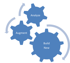
- To instrument existing systems to collect data to justify incorporation into future designs
- To augment existing systems
- To build monitoring into new designs
More generally, any system that meets the desired return-on-investment (ROI) is a candidate for condition monitoring. ROI can and should attempt to account for straightforward factors such as direct downtime costs, as well as more complex factors, such as environmental impact.
There are three primary reasons to consider condition monitoring:
- Reduced downtime: Increases throughput, profit, and staff and customer satisfaction
- Increased safety: Drives down insurance costs and minimizes lawsuits
- Improved environmental impact: Reduces manufacturing waste or prevents impending structural failures
Curious if your system meets the desired ROI for condition monitoring? Download the full whitepaper to understand the direct and indirect costs for condition monitoring and learn how data gathered through condition monitoring can be used to make decisions about your system.
Have more specific questions? Request a condition monitoring consultation with Viewpoint Systems.
Online Condition Monitoring for OEMs – What Is It and How Can It Help Me?

Online Condition Monitoring for OEMs – What Is It and How Can It Help Me?
From a functional perspective, it’s all about indicators and actions
The focus of this article is on small/medium-sized companies (those with less than 500 employees). It is geared toward companies in the industrial space (vs consumer), that manufacture systems or sub-systems (machines, equipment) that are generally more expensive (~$4,000 – $200,000 per unit), and have lower production volume (10’s – 1,000 units per year).
What is online condition monitoring (OCM)?
For the purposes of this article, we’ll define online condition monitoring as the continuous measurement of an asset in-situ to determine its state, generally with the end goal of reducing downtime, increasing efficiency, or reducing waste.
The asset could be an industrial machine (a pump, a generator, a manufacturing tool, etc.), or it could be a piece of infrastructure (a bridge, a pipeline, etc.).
What’s out of scope for this discussion?
- This discussion does not get into online condition monitoring for end users. That is, adding condition monitoring to assets that are used internally. There are many similarities, but they are not the same.
- We’re not getting into the business case for online condition monitoring here, although this is an important element of condition monitoring overall.
How can online CM help you?
We’re going to start with the end in mind. What is the objective with online CM? From a functional perspective, it’s all about indicators and actions.
Indicators:
Indicators include events and fault conditions, and inform you to take an action. These indicators are based on scenario-specific detection algorithms, and tie back to observable anomalies. They might provide indications directly or indirectly related to:
- Bad bearings
- Reduced power quality
- Motor efficiency
- Cracked blades
- Winding shorts.
The list goes on. Indicators could be displayed on a GUI, sent as an email or text message, or sent off to another machine.
Actions:
In response to these indicators, you want to be able to take some sort of action. Actions may include:
- Shut down a piece of equipment immediately.
- Check on or inspect a system further.
- Start collecting additional data for offline analysis.
- You might even use some of the information gathered to feed back into modifications for future product development.
Sometimes an action can be automated directly from one machine to another.
So how does this work?
Online condition monitoring functionally follows this sort of flow:
-
- You start with an asset you want to monitor. You have to observe some useful physical properties, so you have to instrument the asset with the right sensors and mount them in the right spot.
-
- Then, you have to measure that information. To do that, you may need amplification, filtering, or isolation stages prior to A/D conversion.
-
- Then, you process the raw digital data through a series of algorithms to detect good states vs. bad states. These turn into a series of indicators.
-
- Finally, you alert the appropriate people or other machines that something is not quite right and action should be taken.
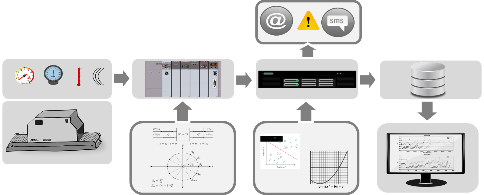
Many scenarios focus on trying to determine if a system needs some sort of maintenance, but you should also consider condition monitoring for scenarios where you can automatically tune the system in order to maintain desired efficiency. For example, maybe you want to monitor the power factor on a power line where there are inductive motors being utilized (which can cause problems for neighboring sites), and instead of stopping at just monitoring, maybe you tune the system by dynamically adding in some capacitance to keep the power quality up.
Additionally, while much of the industry is focused on rotating equipment, CM can be applied to a much broader set of problems. For example, maybe you want to monitor the structural health of a bridge, or the condition of a pipeline.
The key is, if you can reliably detect the problem early enough, you may have a good candidate for online monitoring.
Where you might head from here:
If you’re ready to go deeper with online condition monitoring, check out this guide: Getting Started with Online Condition Monitoring – A Practical Guide for OEMs.
If you’re interested in taking a a step back and want to gain a better understanding of whether or not CM makes sense for your scenario, check out this white paper: Is Condition Monitoring Right For You? , where we’ll provide some basic answers to the following questions:
-
- When should I consider implementing condition monitoring?
- What types of physical properties can be sensed?
- What types of components can be monitored?
- What types of information can be produced?
- How do I translate the information into decisions?
Attention LabVIEW Lovers: Did you know you can do Embedded Development with the NI SOM? – It Still Takes Effort of course
Attention LabVIEW Lovers: Did you know you can do Embedded Development with the NI SOM? – It Still Takes Effort of course
There are three main aspects to consider in order to successfully do embedded development with the NI SOM
You probably went to school for engineering. Maybe you took a LabVIEW class as a MechE or ChemE. Maybe you came up through the test world and now you work in a different capacity in a management role, or maybe you’re an entrepreneur with valuable domain expertise (maybe chemistry, maybe electro-mechanical machinery, maybe high power equipment for the smart grid, or maybe you know the rail industry). However you got here, you’re interested in developing a new embedded product for the industrial side of things (as opposed to consumer, which has its own unique set of challenges). You’ve got a great idea, but you aren’t sure how to get that idea to market. If you’re comfortable with, or have a love for, LabVIEW, there may be a path forward for you: the NI SOM.
There are three main aspects to consider in order to successfully do embedded development with the NI SOM:
- The NI SOM core hardware
- The development environment
- Additional Hardware
NI SOM Hardware
The NI System on Module hardware (the NI sbRIO-9651 SOM) consists of the bare necessities to act as the core processing element, including a processor, memory, some communication interface foundational elements, and an expansion connector. The processor is a Xilinx Zynq SoC, which is a pretty awesome little chip, incorporating both an FPGA and a dual-core ARM-based processor in a single silicon package. Check out the Zynq-7000 devices here.
For more details on the NI SOM, check out here as a starting point, and here for the device specs.
Development Environment
As a LabVIEW lover, this aspect is the main point of interest for you, as you’re comfortable with the graphical programming language (G) that the LabVIEW environment offers. In order to develop your embedded system, you’re going to be spending a lot of time in LabVIEW RT and LabVIEW FPGA (the percentage of each will depend on the specifics of your application of course, but to take advantage of the SoM you’ll need to use both).
However, there may be some low level hardware interfacing that requires the utilization of VHDL (or Verilog). For example, maybe you need access to some primitive within the FPGA (BlockRAM, IDELAY, BUFG, etc). Also, if you’ve got IP from a 3rd party that is in HDL, you’ll obviously be utilizing HDL. Check out this article on Getting Data In and Out of the NI-9651 System on Module (SoM)(especially the Socketed Component-Level Intellectual Property (CLIP) section) for more detail.
If you’re new to LabVIEW FPGA, here’s an intro article: LabVIEW FPGA – The Good, the Bad, and the Ugly. If you’re new to text-based HDLs, here’s another article for you: HDL FPGA Development – The Good, the Bad, and the Ugly.
If you don’t know LabVIEW RT or LabVIEW FPGA, you’ll need to either ramp up on these with some help from NI, or engage someone like a Viewpoint to help you (at least through your first project). The relative difficulty of these various programming methods along with the amount of code you might end up producing (in a very anecdotal / non-quantitative fashion), might look something like the following:
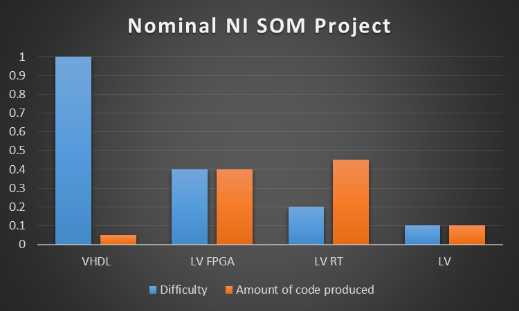
*- very unscientific chart
Note that even though you generally won’t develop straight LabVIEW code for your embedded system, you’ll likely develop some debug panels using LabVIEW.
It’s also worth noting that the real-time processor on the SOM is running a version of Linux. While you don’t need to be a Linux expert, it’s helpful to know some details about your operating system environment, so you can better design your software to work within the constraints of the embedded system. Linux is very powerful, however it does have its own mechanisms to process IO and tasks.
Additional Hardware Needs
If it’s not obvious yet, while the SOM gives you some very important core hardware to start with, you will need to design a custom circuit board to mount to the SOM and connect through the expansion connector. The sorts of circuits you will need will be things like:
- Power supply regulation (e.g., for the SOM components, other I/O components in your system). Some I/O may also require precision references to accurately sample the incoming data.
- Communication interface components (e.g., magnetics for Ethernet, transceiver for RS-232)
- Any I/O interfaces, analog or digital (e.g., signal conditioning, A/D conversion, GPS modules, LVDS translation, digital I/O buffers/drivers, etc.)
If you’ve got the appropriate custom circuit board design capabilities in house, then you have that option. If you don’t have in-house capabilities, or you don’t have the time to develop your own hardware, check out VERDI.
Next Steps
Hopefully this article has given you some things to chew on. Another way to talk about your embedded design is in terms of value layers, as in this diagram:
At the core you’ve got the NI SOM. Layer 1 includes things like the application software and custom electronics. Layer 2 would include the final packaging and integration into the final assembly. A more detailed visual is shown below.
If you’d like help with the NI SOM or anything in layer 1, or if you have questions about industrial embedded development in general, feel free to reach out to us. If you’d like to learn how to reduce development cost and risk with a SOM-based approach, go here. If you’d like more useful info on industrial embedded systems, check out our resources page.
FPGA Gotchas: Four of the top 11 gotchas when developing with an FPGA

FPGA Gotchas: Four of the top 11 gotchas when developing with an FPGA
If you’re just getting started with or are considering utilizing an FPGA on your next project, as with anything complex, you realize you don’t even know what you don’t know.
We recently wrote a white paper on the top 11 gotchas when developing with an FPGA. Here’s a few of my favorites to get you started.
Gotcha #1: Thinking that you’re writing software

Get out of the software mindset – You’re not writing software.
Let me say that again because this is the single most important point if you’re working with FPGAs. You-are-NOT-writing-software. You’re designing a digital circuit. You’re using code to tell the chip how to configure itself. Now, before someone says it, yes, when you’re coding up one of the microprocessor cores within the FPGA, then of course you’re writing software, but that’s not what we’re talking about here. We’re talking about when you’re coding the digital logic.
Gotcha #9: Trying to use all of the FPGA!
In general, you want to use less than 100% of the part. The amount that you’ll want to keep in reserve depends on several factors, with significant factors including:
- The generation/architecture of FPGA being utilized
- Your code quality
- The FPGA clock rate
The fuller your part is, the longer the build process (compile, synthesis, place, route, etc.) will take. The reason this is a useful note, is that build times generally don’t take seconds. Depending on many factors, they can take 20 minutes, or four hours. In some cases it may fail to build at all, or worse yet, build, but be unstable, wasting countless hours in the lab.
Gotcha #10: Not planning for Enough Bugs
Something about that feels wrong on first read, because who actually plans for bugs? You should. If you do it will be one of the most stress-relieving things you do, and you’ll thank me later. You’ll get many of the most basic level 1 bugs out during simulation, but at some point there will be a driving reason where you’ll have to move out to the lab and integrate your part of the world with the rest of the system being developed. This is where those famous words “But it worked fine in simulation…” come into play.
The disadvantage of a run-of-the-mill basic sequential processor is that only one operation is executing at any point in time. The advantage of a sequential processor is that only one operation is executing at any point in time. When it comes to debugging, the sequential nature of the basic processor makes life easier than debugging the parallel nature of the FPGA. While the simulation environment offered impressive visibility, now that you’re moving into hardware, your visibility into what’s going on decreases significantly.
Plan for a lot of bugs. Take a couple hours and think through other bugs you’ve dealt with as an engineer. Now triple that number (I’m making this multiplier up of course). If you’re a newbie developer, you need to pull in someone that has experience with FPGA development to help with this estimate. You’ll be wrong, but you’ll be better off than if you hadn’t thought this through. Here are a few tips on debugging to help you along the way: Six debugging techniques for embedded system development.
Intermittent bugs are common within FPGAs. They can be affected by temperature, humidity, the phase of the moon (I may be exaggerating a bit there, but sometimes I wonder).

The logic analyzer is your eyes into the inner workings of the FPGA. You can view outputs of course, and you can create test points to go to a testpoint header, but you have to be able to probe all of those points, so you’ll probably need a logic analyzer, which can get very pricey (if you’re looking for an inexpensive logic analyzer, check this out: https://www.saleae.com/ , and similar). A logic analyzer is a very important tool for FPGA-based development.
An internal logic analyzer can be helpful as well, at least in some scenarios. You may be able to get away with embedding test resources into your device (e.g. Xilinx has the Integrated Logic Analyzer), but this will utilize FPGA logic and memory resources, and is often challenging to see enough breadth or depth about what’s going on inside your FPGA. However, generally these tools are better for augmenting a true logic analyzer, as opposed to replacing them outright.
Gotcha #11: Making fun of the software guy!
The software guy (or girl of course; the term “guy” is used here androgynously) is your best friend – If your FPGA interfaces to a higher level supervisory sort of processor and/or it provides the UI, the software guy can do things to help make your life a lot easier. A couple of the more major categories include:
- Engineering debug panels – chances are the information you need to view is not the same as what the end-user needs to view. Having a debug panel can save you significant time, effort, and frustration.
- Special debug functions and modes – maybe there is some routine that software normally runs through with steps 1-12, but maybe you want to be able to run just step 3 and 4 repeatedly, or maybe just step 7 once. Or perhaps software can add a special function to keep track of the content or frequency of messages that you’re sending to it and set a trigger when something unexpected happens.
Work with the software developer early on to see how you can work together to facilitate the integration and debug process, and remember that it goes both ways. Chances are there is additional functionality that you could add to aid in their debug process as well.
Next Steps:
If you like these gotchas and want to see the others, read the white paper here:

David LaVine
David was the Marketing Manager & Solutions Architect at Viewpoint. David has a BS in Electrical Engineering from Rensselaer Polytechnic Institute and an MS in Electrical and Computer Engineering from Georgia Tech. He worked at Viewpoint Systems from 2013 – 2019.
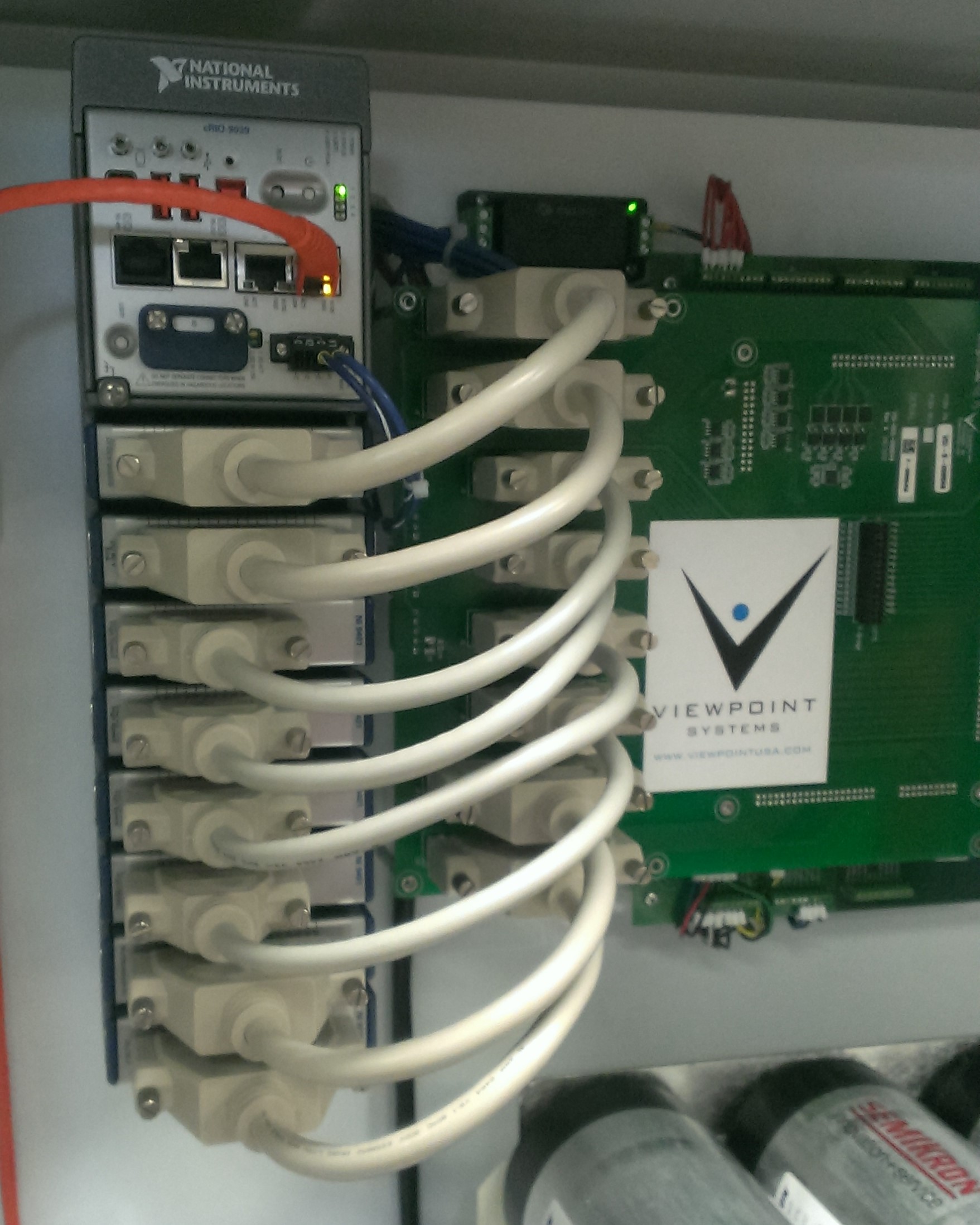
6 Considerations when Choosing an NI RIO for Embedded Systems
6 Considerations when Choosing an NI RIO for Embedded Systems
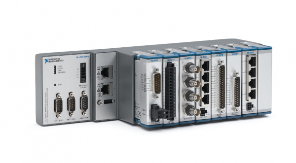
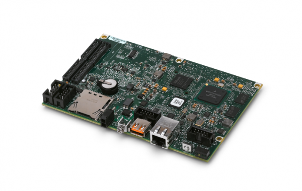
I’d like to share with you the results of a conversation I had at a recent meeting with a long-time client. They wanted to talk about developing a controller for measuring and controlling some aspects of their product. For me, it was a great example of the struggles in development teams when starting a new project using modern tools and components for an embedded system.
Here is some background.
This client has a good, but small, team of engineers who have been supporting various data collection and control systems for many years for support of their (somewhat expensive) machines in the field. (Let’s give this machine a name so we don’t get confused about all the talk of machinery. Let’s use BEM for big expensive machine.)
These engineers have many years of experience putting subsystems in place to monitor the BEMs after delivery to their customers in the field. Some of these subsystems are getting old and obsolete and need to be upgraded, while some are new ideas. The issue is that they, like many other companies, are trying to make their BEMs smarter by attaching new and better sensors to the BEMs and giving the subsystems that use these sensors the ability to control and/or sense the monitoring conditions. The overall goal is to get better information about the BEM performance. It’s actually fancy condition monitoring.
The buzz about the Industrial Internet of Things (IIoT) has these engineers wondering about all those small and cheap embedded processors available today. Heck, you can buy a wireless sensor and cloud data aggregator to monitor your home for water heater leakage and air temperatures for cheap (say about $200 upfront and $100/year)! These engineers are wondering how close they can get to that cost.
So, I visited them to discuss the upgrade of an existing PLC-based subsystem. Let’s call this the OES for Old Existing Subsystem.
They like the NI (National Instruments) platform, and want to start using NI hardware to replace the several types of OESs as well as design new controllers.
During the discussions, we talked about the tradeoffs between the various NI HW RIO options, CompactRIO (cRIO), the sbRIO, and the SoM RIO (the most recent platform), as well as other non-NI options, such as PLCs, Arduino, and so on.
I realized that many other companies must be in the same situation, so I wanted to share some of the important issues that came out of the conversation.
- Don’t go too cheap
- Only need small volumes of about 100 units per year
- Need to balance prototype costs with deployment costs
- Want the units to be supportable for at least 10 years
- Engineering resources are hard to find to design and build the new controller
- Need to support the units in the field for a long time
Some details …
Too Cheap is Not Good
Despite all you hear about cloud-based devices, in an industrial situation, you don’t want to get too cheap on the embedded system. Usually performance specs drive costs and typical “consumer grade” devices won’t have the required operating specs for temperature, measurement noise, shock & vib, and so on.
In this example, the BEM operates in an environment MUCH hotter than the usual office and surrounding equipment can cause vibrations. Furthermore, the measurements need to be accurate to 1% or better, so good quality data acquisition hardware is needed. The NI RIO HW is often a better choice.
Engineering Resources Are Crunched
In the past two years, I’ve seen engineering staffs being increasingly slammed with work. Furthermore, a lot of engineering talent is retiring every year. Companies are turning to outside engineering firms for design and build while maintaining their core capabilities in-house. If you do plan on using an outside firm, do your homework and find a good fit. Bad results can occur if the project is not defined clearly up-front, so be prepared to do some work. Check out this Dilbert comic:
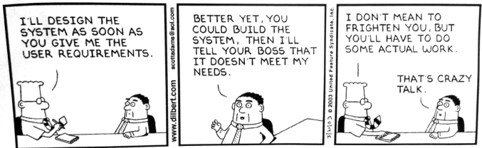
Small Production Volumes
The processors available today for embedded systems are way better than ever before in price per performance. But, often these processors are aimed at consumer markets which sell millions of units per year. For small volumes of a 100s to 1000s per year, a typical (say with 80% coverage) embedded system using NI RIO technology will cost between $500 and $2000 per unit. It’s not yet possible to reach that 100 $/unit mark.
Even with retrofitting all the existing BEMs, the client could not build more than about a couple 100 units per year between new BEMs and retrofitting old ones (they just don’t have enough people to retrofit every BEM in one year).
Support for How Many Years?
Often, the new embedded system is replacing that OES (Old Existing Subsystem) that has been around for way over a decade, perhaps 20 or 25 years. That duration is unlikely now without extraordinary measures to counteract today’s typical subcomponent life cycle of around a maximum of 10 years. I think a lot of this shorter duration is due to the rapid design cycles in electronics. I’m guessing that the photolithography technology used to make electronic components 10 years ago is just not easily accessible anymore!
Tradeoff of Prototyping versus Production Costs
If you are unsure how many units you can sell, then prototype the first units with as much off the shelf stuff as possible. This approach keeps NRE (non-recurring engineering) costs as low as possible but unit costs will be higher than possible. If you know that you can sell at least say 25 units, then consider a using as much custom stuff as possible. This approach has higher NRE but unit costs can be reduced.
The graph below illustrates the two approaches, with the solid line being the off-the-shelf approach and the dotted line being the custom approach.
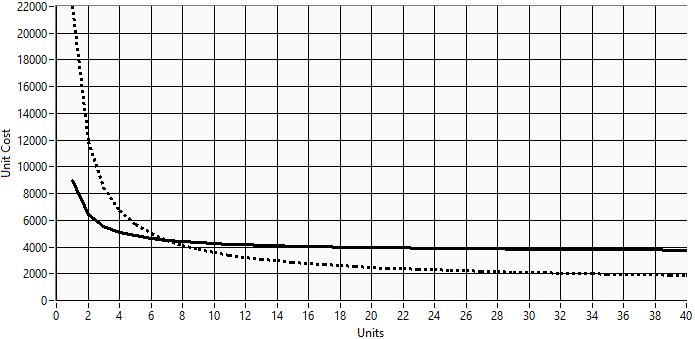
The solid line would be representative of a cRIO approach, while the dotted line would describe the sbRIO or SoM RIO.
Note that hybrid approaches exist. For example, using an already-designed analog input (AI) card designed to work with the SoM RIO can get you closer to the end system than having to wait for the design and build of custom AI circuitry. This approach enables you to prototype your embedded system with modular pre-built parts.
We Have 100s of Units Deployed. Help!!
Often, our clients are very focused on those first few units which will be deployed in a sort of “beta test” program. The thought of having to support 100s in the field is far off in the future. Yet, this support is often the hardest part of an embedded project.
In the case of our BEM manufacturing client, they already know how to support equipment in the field. But with this new embedded controller, they want to use the Ethernet connectivity for remote activities such as controller diagnostics, data downloads, application upgrades, and so on. These activities take time away from future development work and interfere with typical engineering work.
Next Steps
Many companies are looking at ways to embed smarts into their machines. When the total number of units is expected to approach around at least 25, it makes sense to look at a custom-built embedded controller based on the sbRIO or SoM RIO (check out our SOM development platform). I recommend that you prototype with hardware as close as possible to that used in the finished controller while your custom circuit board is developed in parallel. If you are not able to justify the extra NRE (non-recurring engineering) for 25 units, then use off-the-shelf hardware, such as the cRIO (check out our cRIO expertise). If you’d like our thoughts on your scenario, you can reach out to us here. If you’d like more info on the world of industrial embedded, check out our resources page.
How To Build A Business Case For Online Condition Monitoring

How To Build A Business Case For Online Condition Monitoring
Okay, so you think you’ve got a sense that condition monitoring can help you, but aren’t sure how to go about justifying it.
Let’s start by making sure we’re on the same page with what we mean by online condition monitoring. In this context, online condition monitoring (OCM) is defined as the utilization of measurement hardware and software to continuously check the state of a system, a machine, or a process, generally with the end goal of reducing downtime, increasing efficiency, or reducing waste. These goals are accomplished by producing a set of indicators (events, faults, and alarms) that suggest an action, such as looking further into a potential problem, shutting down a piece of equipment, performing maintenance, or collecting additional data. This article is focused on OEM scenarios, but can easily be translated to end-user scenarios as well.
If you’re unsure how to go about justifying OCM, my suggestion is this: utilize the minimum amount of effort necessary. If it makes sense to spend weeks crunching numbers, then so be it, but if it makes sense to tie OCM into a corporate-level initiative (e.g. around efficiency or quality), then go that route.
The level of management buy-in required to proceed will vary significantly, depending on the level of business impact expected from implementation of an OCM system. Justification can be quantitative and/or qualitative.
Quantitative Justification
You’ll need to gather information about the direct, and indirect, impacts of not having OCM on downtime, efficiency, and waste.
This information is scenario-dependent, but many will fall into one or more of these categories:
- Customer uptime/efficiency/waste – if your customers care about how often your machine goes down and if you can tell them in advance, you need to dig in to understand the cost impact on your customer better, in order to better understand the additional cost they could justify for an OCM-enabled product.
- Maintenance or warranty services – if you offer these services to your customer, here are a few opportunities. You could:
- Reduce labor and travel costs by doing more remote diagnostics, only sending out a tech when needed. You’ll need a good handle on your current labor, travel, and possible warranty costs.
- Increase your market penetration by allowing for a more non-linear expansion of number of systems you could provide services for versus number of additional employees you might need to hire. You’ll need to have a good handle on your current labor, travel, and support equipment costs.
- Modify repair schedules based on both yours and your customer’s appetite for risk. This of course requires you to understand the trade-off between material costs, services costs, and costs associated with system failure.
- Future design improvements – you can gather data and statistics that act as a feedback loop for future generations of your product. Information gathered may inform you to loosen or tighten specs on a particular component, or drive you to change a design or a supplier.
Unfortunately, there is generally no easy way for this information to appear at your fingertips. You’ll want to gather information about: labor, travel, downtime, and material costs. This information will come from several business systems and will require speaking with several people, then manually aggregating data. You’ll need to use this aggregated information as a rough cost target for the condition monitoring sub-system. This should only be used as a ROM (rough order of magnitude) estimate. Anything beyond that will likely be wasted effort at this point.
In parallel, you’ll want to develop a ROM estimate for unit costs of the OCM system. You can then iterate throughout the pilot program to converge on a workable solution.
Qualitative Justification:
After reading through the quantitative justification section, you may think that’s your path to success. Not necessarily. If you can justify your case for OCM qualitatively, you may be able to shorten the process to getting your OCM pilot off the ground. Of course, if it makes sense in your scenario, you can always pull both qualitative and quantitative elements to help make your case. Below are some qualitative motivators to consider.
 Sometimes a recent event (e.g. failed customer audit, shipping bad product) can help make the case.
 Sometimes strategic initiatives revolving around efficiency (e.g. lean, ISO 50,001), quality (ISO 9000), environmental impact (e.g. ISO 14001), or safety (ISO 45001) can help you get traction.
 Customer satisfaction – how much is frustration and stress from unexpectedly down equipment worth to your customers?
 Marketing benefits can be utilized to help justify the cost if it differentiates you from a competitor. For example, if your customers are in a manufacturing environment, providing detailed information to their MES systems could be a significant benefit.
Where you might head from here:
If you’re interested in more details about how to get started with online condition monitoring, download our guide: Get Started With Online Condition Monitoring – For OEMs.
David LaVine
David has a BS in Electrical Engineering from Rensselaer Polytechnic Institute and an MS in Electrical and Computer Engineering from Georgia Tech. He worked at Viewpoint Systems from 2013 – 2019.
We’ve helped teams at some of the world’s most innovative companies