LabVIEW Test Systems – Custom Automated Test System Buyers Guide
This guide is for manufacturers of industrial / complex products that need a custom LabVIEW-based automated test system, either for manufacturing test or for product design validation.
Table of Contents
-
Which Platform? (PXI, cRIO, cDAQ , PC)
-
I/O & Signal Conditioning
-
Instrumentation interfacing
-
Test Sequencing / automation
-
Test Steps / application algorithms
-
GUI
-
Automated Report Generation
-
Electronic Records
-
Waste Reduction using Manufacturing Test as a Lean Enabler
-
Data Acquisition
-
Control
-
Enclosures
-
Test Fixtures & Cabling
-
Developing In-house vs Outsourcing
Which Platform? (PXI, cRIO, cDAQ , PC)
What you should know
You’re starting on your test system design, and you realize that the platform options available from National Instruments cover a huge spectrum of capability, so chances are your application will be a good fit for one of the platforms; the challenge is more in figuring out which one is best for your scenario.
NI platforms tend to shine in scenarios where lots of data is being acquired from several channels of different types (e.g., vibration, temperature, pressure, strain, voltage, current, etc.). Does that sound like your scenario at some level?
Gotchas / where people sometimes go wrong
Trying to run a deterministic loop in Windows. Don’t do it. Generally, if you’re loop rate is over a few tens of hertz, you need something more deterministic (like RT or FPGA).
Selecting a PXI, only to use 1/20th of its capabilities, out of concern that a cRIO or cDAQ controller would not have done the trick. PXI is clearly the right choice when you need I/O more than around 64 analog channels or 256 digital channels and have aggregate data rates of more than around a few MBs per second. These numbers are only a “rule of thumb”; other factors such as data processing speed and communications latency need to be considered.
Selecting a cRIO or cDAQ controller with lower capabilities when not sure how much horse-power you need just to save cost. You’ll burn through the cost difference pretty quickly with the extra hours in re-design needed to squish the application into an under-powered controller.
Recommendation / What to do instead
1. Start with a PXI as a baseline, and then convince yourself that you either need to move to a cRIO or cDAQ or perhaps just a PC running LabVIEW.
- A lot of the decision will boil down to whether or not you need a real-time OS and/or an FPGA for determinism in your measurement and/or control.
- Secondarily, the decision will branch on the quantity and fidelity of your I/O needs, with a PC or PXI having modules with higher channel counts sometimes with better accuracy and performance than cRIO or cDAQ.
- If you are at all concerned about processor horsepower or I/O expansion capability, you should lean towards a PXI with a PC as an alternate (you have more I/O choices with PXI, since PCs have fewer slots these days).
- If you are at all concerned about deterministic behavior and OS reliability, you should stay away from a PC running Windows.
2. If you’re new to FPGAs, check out: FPGA Basics – A Look Under the Hood and then FPGA Gotchas.
3. Check out Which NI Platform is Most Appropriate for My Test Needs? for more details.
4. Check out NI Hardware Compatibility – real-world tips and lessons learned.
5. Unless you’re replicating 10 or more test systems, you can likely rule out the sbRIO and SOM; they likely won’t be worth the additional NRE involved, unless a small form factor is a critical requirement.
Check out our NI hardware selection services if you’d like help selecting a platform.
I/O & Signal Conditioning
What you should know
I/O and signal conditioning can be a very specific and deep skill set when you get into things like isolation, filtering, and amplification. If you’ve not dug into the details of converting analog signals into digitized data before, beware of the impacts.
For example, there are huge number of modules available for the different NI platforms (e.g., https://www.ni.com/compactrio/whatis/#io and https://www.ni.com/pxi/whatis/#tab3 )
But, be careful because not all C Series modules are compatible with all C Series platforms: https://www.ni.com/product-documentation/8136/en/
There are of course non-NI signal conditioning solutions out there as well (e.g., https://www.dataforth.com/signal-conditioning and https://pfinc.com/product/28000-signal-conditioners/).
Gotchas / where people sometimes go wrong
A/D conversion – assuming that you can utilize all of the bits of the converter. Quantization noise impacts the lower end of your range. Non-linearities (e.g., in the form of integral nonlinearity & differential nonlinearity) also occur. Noise will consume increasing numbers of bits as your signal to noise ratio degrades.
Cabling/wiring – not following good practices to maintain signal integrity. Crosstalk, poor grounding, lack of shielding, incorrect wire sizing, and impedance mismatches can wreak havoc.
Thermocouples – applying bare TC tips to metal surfaces that can have electrical potential build-up. This potential will appear as additional voltage on your sensor and give you incorrect readings or noise. Also, long leads will pick up EMI noise.
IEPE – forgetting that you can’t measure a DC value when exciting an AC-coupled IEPE sensor.
Transducers in general – bandwidth considerations are often neglected, blunting transients and changing the measured character of fast-changing signals.
Recommendation / What to do instead
- Don’t assume your I/O has proper signal conditioning built in. Verify compatibility with signal levels, impedance, and common mode voltage.
- Check out this book from Henry Ott on noise reduction in electronic systems: https://www.amazon.com/Noise-Reduction-Techniques-Electronic-Systems/dp/0471850683/
- This article is a classic on understanding the sources of noise https://www.analog.com/media/en/technical-documentation/application-notes/AN-346.pdf
- Check out this app note: https://www.analog.com/media/en/technical-documentation/application-notes/41727248AN_347.pdf?doc=CN0397.pdf
- Consider custom electronics designed to interface to your specific sensor or transducer. This approach will create an optimal design including connectivity, cabling, conditioning, and digitization as one I/O package.
Also, check out our NI hardware selection services if you’d like help selecting I/O hardware from NI and other suppliers.
Instrumentation interfacing
What you should know
Depending on your specifics, you may or may not need to interface with external instruments, such as power meters, power supplies, or network analyzers.
Some traditional lab instruments (e.g., DMM, oscilloscope, power supply, SMU, spectrum analyzer, waveform gen) are also available as modules for the PXI.
Often times there are LabVIEW-based instrument drivers available, but the quality of these varies from “it just worked out of the box” to “I would’ve been better off writing my own from scratch”.
Gotchas / where people sometimes go wrong
Assuming that the driver will work out of the box. Unless you’ve already tried it out, plan some number of hours for getting each instrument interface up and running.
Recommendation / What to do instead
- Find out if/what LabVIEW driver exists. Start here https://www.ni.com/en-us/support/downloads/instrument-drivers.html and then check the instrument manufacturers website.
- Don’t assume that, just because a LabVIEW driver is available, you will be able to program the instrument immediately. Drivers take time to learn and, the more complex the instrument, the longer the learning curve, sometimes days or even weeks.
Test Sequencing / automation
What you should know
You can develop your own custom test sequencer (sometimes called test executive) in LabVIEW of course, and for simpler scenarios this likely makes sense.
There are several test sequencers out there (e.g., NI has a test sequencer called TestStand https://www.ni.com/teststand/ , Viewpoint has a test sequencer called StepWise).
Gotchas / where people sometimes go wrong
Assuming you can just dive in and master a sequencing tool in a matter of days or even weeks. There’s a lot under the hood of these tools, so recognize there’s going to be non-negligible ramp-up time.
Not architecting well enough when you want to share resources (e.g., for expensive instruments) across DUTs for N-up testers.
Not architecting for I/O channels operating at different (or asynchronous) rates from one another.
Using a test sequencer when none is needed. If you only test one part on one test system, there is probably no need. If you have multiple test systems that will never share code reuse, UI design, report generation, data archiving and database schemes, perhaps because of your customer requirements, then you probably will not benefit from a test sequencer. Generally, you benefit most from a test sequencer when a single test system is used to test more than one model of parts or when you have many test systems, even those that test only one part model, and want a common user experience across all the test systems.
Recommendation / What to do instead
The decision for creating your own custom sequencer vs using a pre-developed tool generally depends on:
- How many different sequences you need for a given type of test system (is it just one or two, or is it a handful or more?).
- If you operate in a regulated environment (e.g., aerospace, medical, rail) or not.
- The amount of auxiliary functionality (e.g., report generation, revision control, user permissions) you can re-use from an existing sequencer.
Test Steps / application algorithms
What you should know
Test steps and associated data processing algorithms obviously align with the specifications of the product being tested. For example, if the product specs say that the flow rate should ramp from 0 to 5 gpm in 3 seconds, then there will be a test step that measures the flow rate during this “turn on” event. Some specs do should not automatically map to a single test step. For example, testing a spec for maximum vibration amplitude across the operating range of RPMs might require several measurements, each at one RPM.
Gotchas / where people sometimes go wrong
Sometimes people try to include too much functionality into one test step (either based on lack of experience, or just being in a rush). This approach causes issues with debugging and re-use.
If a step’s results are unexpected (e.g., failing more parts than yesterday), understanding the reason for that behavior can be difficult if a step does significant data collection and/or processing.
Recommendation / What to do instead
Writing maintainable and reusable test steps should be the goal. Often, complex test steps can be made more granular, which promotes reuse and easier debug. Product specs that are complicated to validate can often be handled by accumulating the results from multiple, smaller, simpler steps. Following the example above for the test of maximum vibration amplitude across RPMs, a single test step that checks the amplitude at one RPM can be reused at other RPMs, followed by a step that checks the maximum value of the array of test results. Further granularity might include breaking that test step into one that tests that the product achieves the requested RPM (not required by the product spec) and another that measures the vibration amplitude (required by the spec). Plus, now you have a vibration amplitude test step that can be reused for other product testing.
GUI
What you should know
Do you want a thin client running in a browser or a thick client running in Windows, or do you need both?
Younger generations are used to wonderful GUI user experiences (UX) due to mobile app UIs. This will likely elevate the expectation of operator test system GUI UX.
Gotchas / where people sometimes go wrong
Poor UI design can cause false test results from the operator entering the wrong data or ignoring prompts.
Recommendation / What to do instead
- Add forced delays to instruction prompts so operators are forced to acknowledge them.
- Use images and illustrations to supplement text descriptions.
- Obtain user/operator feedback at multiple points during the development process.
Automated Report Generation
What you should know
Consumers of the product or design being tested often love detailed reports of the results. Usually for non-consumer products where the customer is an engineer.
Data analysts love these automated reports since it saves them significant amounts of manual labor. The cost savings for automated reports can often easily justify the expense of the automation.
Gotchas / where people sometimes go wrong
Using the wrong tool and display formatting can make report generation difficult.
Recommendation / What to do instead
- Keep the report layout as simple as possible.
- Include as much automatic data analysis/processing into your report generation as possible. Companies can save a lot of money and time by automating report generation. For complex test procedures, this saving can often be as much as the automation of the test sequence itself saves. Consider having each step render its own section of the test report rather than having a “roll-up” report created at the end of the test sequence execution.
Electronic Records
What you should know
This topic is specific to manufacturing test (vs product validation). Electronic records can reduce errors and increase production rates for products that need to be tested during assembly by manual or semi-automated operations.
Electronic records can be very valuable for customer audits.
Gotchas / where people sometimes go wrong
Designing the records and associated storage for a much smaller number of tested units than ultimately the reality. Be prepared for the additional IT infrastructure and support if production rates increase drastically or the product life cycle extends over a much longer duration than expected.
Recommendation / What to do instead
- Design the records and storage for much larger production quantity than you initially expect.
- Check out the section on reducing errors with electronic documents here: Using Test Systems as Lean Manufacturing Enablers To Reduce Errors & Waste.
Waste Reduction using Manufacturing Test as a Lean Enabler
What you should know
This topic is specific to manufacturing test (vs product validation). We’re talking about Lean-related activities focused on the test system as the enabling component.
Gotchas / where people sometimes go wrong
Two necessary conditions to make any progress in this arena are:
- a point person identified to champion all related activities and
- a corporate culture that reduces some of the hurdles to make operational/process changes.
Recommendation / What to do instead
Check out the section on Waste Reduction using Manufacturing Test as a Lean Enabler here: Using Test Systems as Lean Manufacturing Enablers To Reduce Errors & Waste.
Data Acquisition
What you should know
Data acquisition is a broad topic. As a very high-level introduction, any data acquisition considerations are going to include sensors, signal conditioning, digitizers (analog to digital converters, or A/Ds), and software:
- Sensors convert physical parameters into electrical signals, such as heat, force, speed, current, and so on.
- Signal conditioning is used to take a feeble signal generated by a sensor and boost the electrical output to be compatible with the signal digitizer. It may also supply a current to the sensor for power or ratiometric measurements.
- The digitizer converts the electrical signal into a numeric value which usually needs to be scaled to present the results in the units of the physical parameter you are measuring.
Using force as an example:
- The force sensor is a strain-gauge load cell design which creates a force-dependent resistance change on the sensor.
- The signal conditioning converts this resistance to a voltage in the range of ± 10 V.
- The digitizer converts this voltage to a number, which can then be scaled to force, usually through a gain and offset scaling, if the transducer and all the devices after are linear.
- The software is needed to interface to the digitizer (i.e., the driver layer) and perform the numeric scaling for analysis and archiving (i.e., the application layer).
Gotchas / where people sometimes go wrong
- Sensors are not sensitive enough, resulting in a noisy signal, or are too sensitive, and the output signal gets clipped when too large.
- Sensors have too wide or too narrow a frequency range.
- Signal conditioning doesn’t match the sensor output ranges in both amplitude and frequency and hence distorts the physical signal.
- Digitizer is not fast enough to capture the signal features accurately. Nyquist suggests a sample rate of twice the highest frequency, but often it’s better to consider time-based waveform analysis which requires 10X or even 20X the highest frequency.
- Choosing a digitizer that multiplexes between its many input channels, causing skew in the measurements and electrical crosstalk between signals.
- Inexpensive and improperly chosen cabling and connections between the sensor, signal conditioning, and digitizer can lead to ground loops and EMI-induced noise.
- Choosing software drivers from one vendor and application software from another.
Recommendation / What to do instead
- Make sure that your sensors, signal conditioning, and digitizer are all compatible for the amplitudes and frequencies you want to measure.
- If you can afford the extra cost, use a digitizer with simultaneous A/Ds, since they have no channel skew and crosstalk.
- Design the cabling and connections properly to minimize ground loops and EMI interference.
- Choose software drivers and application software from one vendor or choose a hardware vendor that has a good reputation for supporting multiple standard development environments.
Control
What you should know
Control is a broad topic, perhaps even broader than data acquisition. As a very high-level introduction, any control considerations are going to parallel data acquisition but in reverse, where:
- The digitizer is replaced with a digital to analog converter (D/A),
- The signal conditioning converts the D/A voltages into the appropriate levels and possibly supplies a current for power to the actuator,
- And the sensor is replaced by an actuator to provides a physical stimulus.
Actuators convert electrical signals into physical parameters, such as heat, force, speed, and so on.
Using heat as an example, the heat actuator is a set of heater coils that radiate heat in proportion to the DC current applied to them.
- The digitizer converts the heat value into a voltage, typically in the range of ± 10 V, by scaling, usually through a gain and offset.
- Then, the signal conditioning converts this voltage into a current compatible with the heater coils and then coils radiate at the commanded heat flux.
- And, finally, software drives this conversion through a driver to the D/A electronics and application software than manages the conversion of physical to electrical values.
The other aspect of control is the need for a control algorithm. The situation just described is open loop control: the heater outputs heat at the commanded heat flux, but the temperature of the object you are heating depends on the environment in which it resides. Close loop control would measure the temperature of the object and an algorithm would adjust the output current to the heater to achieve the desired temperature.
Gotchas / where people sometimes go wrong
- Actuators are the wrong sensitivity, resulting in too small or too large an output.
- Actuators have too wide or too narrow a frequency range, causing “jitter” in the former and sluggishness in the latter.
- Signal conditioning doesn’t match the actuator input ranges in both amplitude and frequency and hence distorts the physical signal.
- D/A is not fast enough to output the signal features accurately. However, actuators are usually slower than the D/A.
- Inexpensive and improperly chosen cabling and connections between the actuator, signal conditioning, and digitizer can lead to ground loops and EMI-induced noise.
- Choosing software drivers from one vendor and application software from another.
For close loop control:
- Loop rates can be too slow for the sensor and actuator to follow the desired setpoint changes. Or the sensor and actuator can be too slow to allow the control loop to work properly.
- If the control loop updates non-deterministically, the control will be “noisy”.
- If the actuator is too sensitive, the control will be difficult. For example, consider trying to maintain the level of fluid in a small 1 liter tank when the inlet valve outputs 1000 liters per second: the bottle completely fills in less time that the control loop can update.
Recommendation / What to do instead
- Make sure that your actuators, signal conditioning, and D/As are all compatible for the amplitudes and frequencies you want to measure.
- Design the cabling and connections properly to minimize ground loops and EMI interference.
- For closed loop control: select loop rates compatible with the actuator and sensor time responsiveness and use a deterministic environment to execute the control loop algorithms.
- Choose software drivers and application software from one vendor or choose a hardware vendor that has a good reputation for supporting multiple standard development environments.
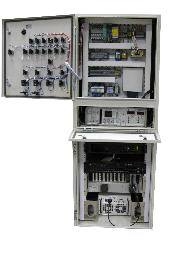
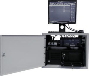
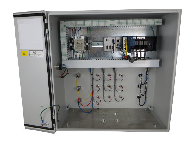
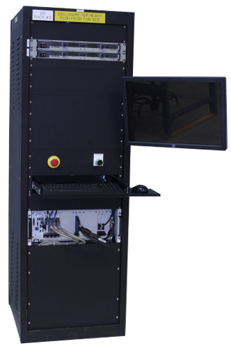
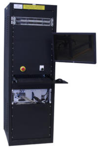
Enclosures
What you should know
Enclosures are used to protect all the signal connections and data acquisition equipment. Often times enclosures require some sort of well-known standard to be applied to assure operational safety, reduce ingress of water or dust, or reduce electro-magnetic interference.
Some standards you may be interested in:
- NEMA, IP and IEC 60529 rating requirements
- UL 508A, CSA, and others
- NFPA 70E, ATEX, and others for hazardous locations
- CE Mark
Gotchas / where people sometimes go wrong
- Poorly designed access to components after build makes maintenance challenging.
- Overheating of internal components due to inadequate ventilation. Especially challenging when dust and fluid ingress is restricted.
- Not considering the physical location for mounting.
Recommendation / What to do instead
Get a qualified and experienced panel/enclosure designer and builder to manage any enclosures you need.
Test Fixtures & Cabling
What you should know
Good specifications on signal types, levels, and bandwidths. You’ll want to know whether the signals are differential or single-ended, the amount of current they might carry so proper wire gauge can be used, and that long length will reduce the signal bandwidth the cable can realistically carry.
Expected number of make/break cycles on connectors. Connectors that are reconnected many times, say to a unit under test, will quickly lead to poor signal fidelity if that connector can tolerate only a few cycles.
Environmental considerations must match enclosure requirements. If the enclosure needs to withstand water spray, then the cable connections should too.
Gotchas / where people sometimes go wrong
Using a rat’s nest of cables when a more sophisticated harness, ITA (Interface Test Adaptor), or custom test fixture probably would’ve been better in the long run. The hours spent debugging when an incorrect connection is made can quickly offset the cost of the cheaper rat’s nest of cables.
Recommendation / What to do instead
- Utilize COTS cables as often as possible
- Use an ITA to manage the connections, such as SCOUT from MAC Panel
- Use wear-cables if number of expected make/break cycles exceeds connector specifications
- Consider using a custom PCB in place of cables when UUT cables need to transform into test system cables. This approach is often less expensive than custom cables to mate the two pieces of hardware. The SCOUT platform can house that custom PCB.
- Consider combining signal conditioning and cabling with custom electronics. Custom electronics can help with connectivity, impedance matching, voltage levels, filtering, and so on.
Developing In-house vs Outsourcing
What you should know
A good way to decide whether to develop your test system in-house or outsource is to ask yourself:
(1) Do we have the expertise?
(2) Do we have people available?
If the answer is yes to both of these, then you’ll likely want to do the work in house (there’s still a potential argument to be made about how expensive in-sourcing vs outsourcing would be for the project, but most people don’t like that argument)
If you’re thinking of outsourcing:
- There are hundreds of LabVIEW consultants out there available, so depending on the level of support and capability you need, many may be sufficient.
- There are ~dozens of true LabVIEW system integrators. There is a decent amount of overlap in capability, but generally larger integrators do focus some amount on particular industries or applications (e.g., RF test, dynos, electro-mechanical test). An integrator’s website may give you some indications as to their focus areas. Remember, system integrators work on custom systems, so they’re used to dealing with a variety of industries and applications. The key is how efficiently you can talk with each other in the same language.
Gotchas / where people sometimes go wrong
Using price as the only deciding factor. Price should absolutely be a factor in your decision process. You just don’t want it to drive you into a direction that either (1) boxes you into a corner you don’t want to be in or (2) gives you a solution that doesn’t meet your needs. Is there a reason that one price is significantly different than another?
Using location as the only deciding factor. All other things being equal, it’s obviously easier to work with someone within a couple hours of you. However, all other things are generally not equal. You need to weigh proximity against other factors, including capability, price, and ease of working with.
Not knowing that some integrators are better to deal with when requirements are not well-defined. Specifically, some integrators follow a business model that defaults to requesting money up front in ill-defined projects. If your requirements are incomplete, a better approach is to find an integrator that is ready for some preliminary design approach discussions, at no charge, before locking down requirements. This approach often leads to an outcome is a more cost-effective solution than your original conception.
Recommendation / What to do instead
See 9 Considerations Before you Outsource your Custom Test Equipment Development for more details.
Some topics we’ve not covered here, but are definitely worthy of consideration include – calibration, data storage, safety, cybersecurity, system configuration, diagnostics, documentation, training, installation, and warranty. If you’d like help with your next LabVIEW-based automated test system, feel free to reach out. If you’re looking for more helpful resources, go here.
If you’re deep into learning mode, here’s some other resources for you:
- 5 Keys to Upgrading Obsolete Manufacturing Test Systems
- Aerospace Test Bench Design – real-world insights
- Hardware Product Testing Strategy – for complex or mission-critical parts & systems
- Test Automation Best Practices
- What is LabVIEW? – A developer’s perspective
- Which NI Platform is Right for Your Automated Test Needs? cRIO, PXI, cDAQ, sbRIO?
- How to prepare for when your test team starts to retire
- Practical manufacturing test and assembly improvements with I4.0 digitalization
- What to do with your manufacturing test data after you collect it
- How Aerospace and Defense Manufacturers Can Make the Assembly and Test Process a Competitive Advantage
- Reduce Manufacturing Costs Report
- Improving Manufacturing Test Stations – Test Systems as Lean Manufacturing Enablers To Reduce Errors & Waste