Custom Automated Test Systems for Electrical Components and Systems
Electrical component test systems often need industry-specific components to complete the test system.
Low-power components can often be tested with straightforward signal conditioning for connections to data acquisition hardware. For example, testing battery or fuel cell stacks up to a few 10s of volts can be handled with isolation modules which offer common mode rejection.
For high-power components, the signal conditioning can involve some potentially large and expensive components. Furthermore, safety considerations become paramount via both proper component selection, guarding, lockout-tagout procedures, and possible shutdown control schemes. These high-power situations also often call for careful design of signal grounding and shielding to reduce noise on the measurement signals.
We develop custom automated test systems to test electrical components and systems.
From high-voltage power supplies, to industrial-grade UPSs, high-power capacitors to electric motors, from power meters to fuel cells, and from power conversion switches to regenerative blowers, we’ve tested a lot of different electrical products.
How we can help: our capabilities & expertise
Want more proof points? Check out these case studies:
Fixing and Updating TestStand & LabVIEW for a New Power Distribution Product
Fixing and Updating TestStand & LabVIEW for a New Power Distribution Product
Dealing with frustration from a prior development effort and wanting to update testing capabilities with LabVIEW and TestStand
Client – Starline, a Brand of Legrand, a global leader in customizable power distribution solutions
Challenge
In their ongoing pursuit of high-quality products, Starline, a Brand of Legrand, wanted to regression test the firmware being developed for the M70 Critical Power Monitor, one of their new electrical power metering products. Starline requested Viewpoint to step into a project that was already underway.
Starline had existing TestStand / LabVIEW code already in place from a prior generation of the meter, but it had performance issues and, more importantly, it didn’t support the next generation of product. The existing code was developed both internally and externally in collaboration with another system integrator; however, Starline was in search of a new partner to help take the project across the finish line.
We needed to quickly learn the existing codebase to deliver the requested enhancements while rebuilding trust after Starline’s difficult experience with the previous system integrator.
Solution
Starline developed a detailed Statement of Work as guidance for the outstanding tasks. The initial scope was directed at supporting the new product line, which the existing software did not include.
Going through the process of learning the existing software, we noticed several areas in which the code was ”fragile” due, in part, to:
- Inadequate architectural design choices,
- Duplicated code blocks, which complicated bug fixes and maintenance,
- Telnet comms rather than more basic serial comms,
- Misalignment in capability between the test software and the product firmware,
- False Pass conditions due to inadequate error handling, and
- UI complexities, which made it challenging for the operator to manage the test flow.
In collaboration with Starline, we agreed to strengthen the architecture and codebase before introducing new capabilities, then return to the original objective of supporting the new products.
Working Together
We were able to gain Starline’s trust by showing them our collaborative process through resolving issues within the existing code architecture and code base. We were then able to work together to define the tasks required to correct these issues.
Throughout the work, project management went smoothly. Starline’s project manager was detail-oriented, engaged, and approachable. Software tasks were managed with Jira and tasks were reviewed at weekly status meetings. This approach ensured that all issues were being tracked and that everyone was aware of progress being made to resolve them.
Our involvement in this project was completely remote (i.e., we were ready to go on-site but it was not needed). Admittedly, there were minor challenges around this work arrangement, but we were able to work together to iron out the wrinkles. For example, because the firmware was still in development, sometimes the Unit Under Test (UUT) would freeze due to a change in the latest firmware. A reboot of the UUT was needed, which required a person to power cycle the UUT. After a discussion, we decided to expose the soft front panel of the power supply so we could remotely power-cycle the UUT.
This simple and cost-effective solution helped illustrate the importance of a great relationship between the test system integrator and the client.
Benefits
How we helped
We were able to help Starline by providing:
System Overview
The new product line is aimed at supporting the ever-growing need for high-density power in data centers, high performance computing, and AI centers by providing data on real-time voltage, current, and power. Standard communication protocols are used to ensure seamless integration with virtually any Building Management system (BMS) or Data Center Infrastructure Management system (DCIM).
Since the product and its various configurations were completely testable through various communication protocols, the test system was able to run all tests by sending commands to the unit and reviewing its responses.
In the real world, certain configurations of the product would connect to external equipment, or the product might have some additional subassemblies installed.
Starline determined they would develop special firmware to simulate these additions. This prototype test firmware would simulate responses to messages as in the real-world. In similar fashion, faults were simulated with this prototype test firmware. Then, the test system was able to test all configurations, real and simulated, for a comprehensive exercise of the product’s firmware.
We used both serial RS-485 and Ethernet for baseline communications with support for several protocols, such as:
- Serial RS-485
- SSH
- ModbusTCP
- ModbusRTU
- BACNet
- SNMP v1
- SNMP v2
- SNMP v3
- SNMP v3 Traps
Because our involvement was requested after the project had already been started, Starline provided the test system hardware and initial software. Our job was to refactor, clean, and add functionality to the software to test the new product’s firmware.
| SOFTWARE FUNCTIONS |
|---|
| TestStand |
| LabVIEW |
| HARDWARE USED |
|---|
| USB to RS-485 serial converter |
| Ethernet |
Enhancing an existing test system for ease of maintenance
Enhancing an existing test system for ease of maintenance
Reduction of time and frustration motivates software upgrade of a capable but inflexible test system
Client – A world-wide manufacturer of refrigeration units
Challenge
Our client had been using a 15-year old test system LabVIEW-based application that was becoming difficult to update. Plus, the designs of their newest refrigeration units were more complex than ever, requiring new test steps.
On top of that, our client wanted to give the operator flexibility in sequencing the test steps. For example:
- the operator might want to run a specific test twice to verify operation,
- the operator might want to restart a sequence in the middle after reworking a part, or
- the test engineer might want to add another test step to further clarify operational data for historical trend analysis.
The existing application was based on a state machine architecture. While state machines can be edited to handle different sequence flows, this test application had numerous alterations over the past 15+ years to support the needs for testing new product designs. These amendments compounded over the years into an unwieldy test application.
New products were about to be introduced which would require additional modifications to the existing state machine and subsequent verification that:
- changes worked as planned and
- changes didn’t affect any other existing modes of operation. This need was increasingly daunting.
The Design and Development Process
Very early in discussions, we showed our client a test application based on an object-oriented (OO) software architecture, and its associated user interface, that we had used in previous test system projects for other clients. We thought it might satisfy some of the desires we were hearing about:
- how the older state-machine-based test system was difficult to maintain,
- how some users were frustrated by the inflexibility of the test sequencer, and
- wondering why the system can’t be easier to update for new product requirements.
Moving the existing application over to this new architecture would clearly require more effort than another patch, so we had to decide if the cost for this approach would be justified based on two major benefits:
- Simplify the management and verification of future changes.
- Enable flexible test flows to give the test operator a better user experience.
Both benefits would accumulate cost savings for maintenance and upgrades going forward. After discussions with our client, we jointly decided this approach was justified.
After reviewing this OO approach, our client asked us to use it to develop a small test system for another component of the refrigerator products. This small system gave our client the chance to explore the “look and feel” of this new architecture and user interface design before embarking on the test system discussed in this case study.
That trial project was a success, and we were given the go-ahead. The benefits, as described above, were clear.
After the development was complete, we:
- worked with our client on integrating the test system into the existing test station,
- performed acceptance testing, and
- delivered the final items, like source code, to our client.
Solution
The initial upgrade tasks in creating this new application started by identifying the code for the test steps in the existing test application, which was based on that state-machine architecture, and then rewriting the test step functionality with the OO methodologies discussed earlier.
We also reworked the sequencing of steps to use an OO-based test sequencer. The test sequencer was reused from some of our prior projects.
For each test step in the existing test application, we repurposed the existing LabVIEW code in two ways:
- First, we identified code functionalities that were commonly used throughout the state machine for the purpose of defining a set of reusable step types.
- Second, we converted that common functionality into LabVIEW classes via copy-paste into the class methods, coupled with extraction of the configuration parameters needed to give each class the behavior needed for a particular step.
For example, the existing state machine contained many steps that provided a request-response method over a data bus. These similar steps were corralled into a single class with methods for data communication. Thus, each of the multiple original states in the existing application which requested parameter values could be made by calls to the same class in the new application simply by providing specific configuration inputs to the same class method.
Benefits
This OO design simplified updates to the test steps and their sequencing.
Furthermore, the operator interface was simpler, cleaner, and allowed the operator to manage the flow of the test steps. For example, operators could jump around in the test sequence when needed, say for reviewing the occasional confusing result or helping to develop the production test sequence.
The OO design of this new test system application was aimed squarely at improving the user experiences of both the operator and test engineer. Secondarily, the OO design will help the test system developer by untangling the original state machine code into supportable, extensible, and maintainable software.
Some specific benefits available from this new OO design:
- Reduced frustration – If the operator noted something confusing about the outcome of a test step, that step can be rerun without needing to restart the entire test sequence.
- Improved operational efficiency – The operator and/or test engineer can try a different sequence of test steps for operational or efficiency improvement.
- Faster test system updates – Two aspects make updates faster and cleaner. First, new product designs can be accommodated with less worry about whether the fragile state machine code will break, Second, the code modularity of OO test steps makes it easier to implement new tests.
These usability and maintainability features will save our client cost and schedule in future product upgrades as well as highlight the contributions of the test system on production efficiency.
System Overview
The test hardware was based on NI CompactDAQ and the application was written in LabVIEW. The automated test system provided the following main features:
- Test configuration based on the type of part being tested
- Test sequencing with part-specific test steps
- Test sequence execution can be managed by the operator in real-time
- Display of test results as the sequence progresses
- Archiving of test data for historical tracking
The test flow that this application runs is:
- The operator enters the model and serial numbers (typed in or scanned in).
- The test system looks up the model number and finds the test sequence to run.
- The test system populates the sequencer screen with the appropriate test sequence.
- The operator can select a step from which to start or just click the Start Test button to begin the entire sequence.
- Buttons at the bottom of the sequence display allow the user to Pause, Abort, or Resume the sequence.
- Executed test steps are highlighted in green (pass) or red (fail) to indicate how the sequence is progressing. The operator can scroll through the test sequence to review the outcome of each step.
- If the sequence is configured to do so, the sequence may pause at a failed step so the operator can repair and retest that step.
The unit under test (UUT) was monitored by the test system to view sensors both internal and external to the UUT. The external sensors are used to detect the environment of the unit, such as being in position, connected to power, and so on.
Besides a few thermocouples and digital inputs, measurement data used to determine pass/fail was obtained from the UUT via the data bus.
All these inputs were handled by a set of NI modules in a 4-Slot cDAQ chassis.
| SOFTWARE FUNCTIONS |
|---|
| Data communications |
| Acquire sensor data |
| Control digital output |
| Acquire digital inputs |
| Test sequence management and execution |
| Archiving of all test results |
| HARDWARE USED |
|---|
| 1 Port High Speed Communication Module |
| 8 Channel AI Module |
| 8 Channel Sourcing DO Module |
| 8 Channel Sinking DI Module |
Custom Automated Test System – Characterization of Heat Transfer System Thermal Performance
Custom Automated Test System – Characterization of Heat Transfer System Thermal Performance
R&D testing required flexibility in control schemes and measurement I/O
Client – ATSI, a large-scale System Engineering Provider
Challenge
Our client, ATSI, Inc., headquartered in Amherst NY, designs and builds complex structures and process systems, from industrial construction projects to mechanical systems for power engineering. A previous, long-standing Viewpoint customer that does research and design of thermal energy systems approached ATSI to engage in the build of a specialized test skid that would be used to assess and characterize a heat transfer system. Our long-standing end-customer requested a data acquisition subsystem based on LabVIEW.
Furthermore, the end-customer requested a subsystem that supported flexibility in the data acquisition by channel count and type, since the R&D nature necessitated adaptability. The overall test system needed to automate progress through a sequence of setpoints and ramps.
Solution
ATSI designed the automated control and sequencing with a Modicon PLC. Viewpoint augmented ATSI’s engineering resources to provide the data acquisition subsystem and setpoint sequence editing. This sequence was passed to the PLC for automated sequencing thought the setpoint list. Because our mutual end-customer did not provide explicit design details about the hardware needed for data collection and control, we had flexibility to decide which aspects of these needs would be automated by the Modicon PLC and which by the PC running LabVIEW.
Since Viewpoint had previously developed a similar application for our mutual end-customer, with some of the required data acquisition needs, we chose to leverage and enhance that software platform for this project. That choice drove some of the other designs and defined the scope of work for Viewpoint and ATSI. Specifically, we worked with ATSI to select NI hardware appropriate for sampling all the high-speed data, since the PLC would not be capable, and some of the slower speed data, which needed some specific signal conditioning. Other very-slowly changing process parameters were read from PLC tags.
Some overall design decisions were:
- The LabVIEW application provided data acquisition, test configuration, and operator screens.
- The Modicon-based subsystems provided process control and safety.
- A PLC HMI for process system operation and status as well as control loop tuning.
- NI Compact DAQ (cDAQ) offered flexible PC-based acquisition channels for high sample rate historical data collection.
- A sequence editor on the PC defined the test setpoints, durations, and limits to pass to the PLC for execution.
The test configuration encompassed cDAQ channel configuration, PLC tag configuration, sequence editing, and graphical views on the acquired data. Some channels were acquired at slow rates, e.g., up to about 1 S/s for sensors measuring parameters such as temperature and flow, while others had fast rates, e.g., 1 kS/s to 10s of kS/s for sensors measuring parameters such as transient pressure and vibration. Handling the datafile storage and display of this wide range of data types and rates was important for the end-customer to compare and correlate the effects of changing operating conditions.
Data logging is configured by the sequence editor to occur on certain conditions such as immediately entering a new step, time delayed after entering a step, and activated by the PLC upon reaching stable setpoint control. This flexibility gave the end-customer management of when data collection occurred to ease the comparison and correlation of readings from selected sensors.
After the configuration is completed, the sequence is passed to the PLC. The operator starts the test on the PLC HMI and the PLC automates the test run. Data collected during the test run could be displayed in live graphs during testing, used for verification of setup and operation; post-test in stacked graphs and overlaid plots; and exported for specialized analysis, display, and review.
Benefits
The design of this system was driven largely by the need for flexibility. Sensors and channels could be added, the test sequence could be edited with a variable number of steps with editable execution features, and the data acquisition and storage permitted various rates and logging criteria.
These design choices offered the following advantages:
- As a partner of the team, Viewpoint acted as staff augmentation for ATSI by providing experienced engineers with expert LabVIEW and data acquisition capabilities.
- Flexibility of test sequences, including setpoints and their stabilization criteria.
- Tight integration between the Modicon PLC and LabVIEW-based PC enables critical control and safety to execute reliably and yet adjustably.
- Customized mechanical all-welded skid plugs into end-customer’s test article.
- Setup of data logging including configurable sample rates.
- Ability to add channels by plugging in supplemental DAQmx-based cDAQ modules.
- The LabVIEW application architecture is actor-based for straightforward inclusion of new data sources as needed in the future.
- New data sources are registered with the object-based data aggregator.
- The system handles multiple days of test execution
- The multi-pronged viewer allows verification checks while in setup an operation as well as post-test review.
System Overview
The custom automated test system supplied to the end-customer was a hybrid, made up of PC-based and PLC-based components coupled with the fluid-handling components on the skid. The hardware listed below includes only the data acquisition, control, and safety items, and only a high-level description of the mechanical aspects.
| SOFTWARE FUNCTIONS |
|---|
| NI LabVIEW for Windows [Viewpoint] |
| NI LabVIEW Modbus driver [Viewpoint] |
| NI DAQmx hardware drivers [Viewpoint] |
| Actor-based object-oriented LabVIEW application for the PC [Viewpoint] |
| Modicon Concept software [ATSI] |
| Blue Open Studio HMI software [ATSI] |
| Function Block Programming for the PLC [ATSI] |
| HARDWARE USED |
|---|
| Modicon PLC and modules for pressure, temperature, flow and other process variables |
| NI Compact DAQ chassis and modules, e.g., 4-20 mA, RTD, thermocouple, thermistor, and 200 kS/s analog input |
| 600 VDC Power supplies |
| Components to flow fluid, including pumps, valves, pressure regulators |
| Intel Tower PC for LabVIEW |
| Mini Industrial PC for HMI |

Industrial Monitoring for a Harsh Environment
Industrial Monitoring for a Harsh Environment
Developing an industrial monitoring system for ultrasound-based sensing in a harsh environment
Client – Energy Research Lab
Challenge
Our client was experiencing problems making temperature measurements in a hostile, irradiated environment. Traditional temperature sensors don’t last long in this environment, so our client was developing a sensor designed for these conditions.
Special equipment is required to drive this sensor. It’s an active sensor requiring an ultrasound pulser/receiver (P/R) and high-speed digitizer to make it function.
The prior attempt the client made at using an original set of special equipment was having reliability and connectivity issues. This reduced reliability was of critical concern due to the requirement for the sensor to operate for years without downtime.
In addition, the existing application was incapable of displaying live data and lacked a user-friendly interface. On top of that, data analysis had to be done after the application was run, causing delays.
Our client needed reliable and robust hardware to drive the sensors and an application that would eliminate the challenges associated with the existing system.
Solution
Viewpoint accomplished the following:
- Evaluated two different ultrasonic P/R sensor driver hardware solutions to select a solution that would provide the connectivity robustness, configurability, and correct sensor driver characteristics required for the given sensors.
- Decoupled the digitizer embedded in the original P/R by adding a PXI digitizer with better capability.
- Provided backward compatibility with previous measurement hardware to aid in performance comparisons with the new hardware.
- Developed a LabVIEW-based application that corrected all the issues with the existing application including real-time data analysis, real-time data visibility and a modern user interface. The new application also provided sensor performance traceability using the sensor’s serial number.
We selected the NI hardware and non-NI equipment to assure compatibility.
Benefits
The enhanced measurement system offers the following benefits:
- Reliable sensor subsystem to ensure uninterrupted data acquisition.
- Measurement hardware configurability for sample rate, collection duration, and pulsing repetition rate.
- Application configurability for automating the analysis, historical archiving, and results reporting.
- Real-time data analysis.
- Sensor traceability through serial number and data files.
- Engineering mode to take control of the entire measurement system.
- Improved data logging to include raw and analyzed data.
- Improved application user experience via robust data collection and configurability.
System Overview
The deployed temperature monitoring system consisted of the following components:
- COTS pulser/receiver hardware for driving the sensors.
- COTS high-speed DAQ for retrieving ultrasound signals.
- A LabVIEW-based software application to provide real time data monitoring, error/alarm notification, data analysis, data logging, part traceability and backward compatibility with the older sensor driver hardware.
| SOFTWARE FUNCTIONS |
|---|
| Acquire Data from Sensor Driver Device |
| Data Analysis |
| Write Raw Data to File |
| Write Analyzed Data to File |
| Configuration Utility |
| HARDWARE UTILIZED |
|---|
| Sensor Pulser/Receiver Driver |
| NI PXIe Expansion Chassis |
| NI PXI Oscilloscope Module |
| NI PXI Thunderbolt 3 Module |
| INTERFACES / PROTOCOLS |
|---|
| RS-232 |
| Thunderbolt 3 |
Increasing Test System Automation for Existing Tester to handle Production Volume Demand Increase
Increasing Test System Automation for Existing Tester to handle Production Volume Demand Increase
Reduced test time across several products by an average of ~25% and reduced time to create paperwork by ~3x
Client
Manufacturer of high-voltage power supplies
Challenge
The client already had an existing manufacturing test system in place. They wanted Viewpoint to enhance the tester due to an increase in production volume demand. Viewpoint reviewed the existing test system and noted 3 areas for improvement:
- Automation available in the measurement instruments – most of the test equipment was automatable, via some combination of serial, GPIB, or Ethernet interfaces. Furthermore, some equipment, such as an oscilloscope, had the ability to store and recall setup configurations. The test operators already used these configurations to decrease setup time for the next test step. Most test equipment did not have automated setup.
- Operator time spent on each test step – the client had been through a Lean assessment and had already done a good job of timing operations. However, we specifically noted that the operator was manually connecting to the test points and manually transcribing to paper the measurement results from instrument displays.
- Automating the connections – many types of product models were being tested at this test system. Connecting the test equipment to all sorts of products would require either 1) many types of test harnesses and connectors or 2) a redesign of the products to make test connections simpler and quicker.
Solution
The enhanced automated test system included automation of instrumentation interfaces, a test executive to run the test sequences, automated test report generation, and automated test data archiving for the electronic UUT.
Benefits
- Reduced total test time across several products by an average of ~25%.
- Time to create paperwork was reduced by ~2/3 due to automated data collection.
System Overview
The enhanced test system included the following updates:
- Test sequence automation
- Automated test report generation
- Automated test data archiving
- Automation of instrumentation interfaces
- Configurable automated test steps associated with each type of measurement instrument. The test operators would create a sequence of steps to setup each instrument and record the resulting measurement. The sequence of steps could be saved and recalled for each product to be tested, so the instruments could be used automatically.
- New programmable meter – integrated the new DMM meter with a programmable interface to replace the one that was not automatable.
- Foot switch integration – Since the connections to the test points were manual, a foot switch allowed the operator to take the measurement and advance to the next step.
The StepWise test executive platform managed the multiple test procedures created for the different products. StepWise also handled creation of HTML reports for every part tested.
| SOFTWARE FUNCTIONS |
|---|
| Test GUI |
| Test Sequencer |
| Report Generator |
| Test Data Archiving |
| Instrument interfaces |
Designing an Automated Fuel Cell Validation Test Stand
Designing an Automated Fuel Cell Validation Test Stand
Verifying a New Fuel Cell Design Through Automated Operation
Client: A major automotive manufacturer
Problem Scope
Micro Instrument, an automation vendor that builds product validation and test stands, has extensive experience with programmable logic controllers (PLCs) and stand-alone controllers for controlling repetitive motion, safeties, and other “environmental” parameters such as pressure and temperature. The company typically uses PLCs to reliably deliver discrete I/O control and standard PID loop control.
However, Micro Instrument’s customer, a major automotive company, was interested in investigating fuel cells as a power source and they needed to run these fuel cells under a wide range of conditions for extended durations, for both design validation testing and durability testing purposes. These fuel cells required more advanced control algorithms than could be provided with a simple PID. A more powerful controller was needed.
Challenge
The customer knew they needed control loops that predicted system response so we could eliminate overshoot and/or achieve a faster approach to a setpoint. But, because the customer did not know in advance exactly what such “smart” controls would entail, it was beneficial to have the full power of LabVIEW to develop such controls. Providing this functionality with a PLC would be cumbersome, if not impossible.
The customer had some Compact FieldPoint which they wanted to use for this project, so we needed to ensure that this equipment would be sufficient to deliver the required control performance and tolerances. Also, the system needed to conduct PID control in two forms – PWM and continuous control. Importantly, this Fieldpoint hardware had a real-time controller running LabVIEW Real-Time.
Solution
The test system we developed included a 19″ rack test stand populated with fuel piping and control, power supplies, harnessing, data acquisition and control hardware. This hardware was a NI Compact FieldPoint controller, chassis, and modules. The Compact FieldPoint controller was programmed with LabVIEW Real-Time to meet the customer’s system control demands. For example, to predict system response, we programmed the Compact FieldPoint to run control loops that were aware of imminent system-state changes and changed their control schemes accordingly.
As with most validation test systems, we needed to monitor conditions for safety. New product designs are often operated near the edges of safe operation in order for the designer to understand how the product performs in extreme conditions. For this fuel cell application, destructive over-heating and over-pressure could occur. Both digital and analog signals were watched in real-time to assure operation within reasonable bounds and allow a safe shutdown if the fuel cell ran into out-of-bound conditions.
The application used the following independent parallel loops:
- Seven for PWM-based temperatures control
- Two for continuous pressure monitoring
- Four for solenoid and sensor monitoring and control
- 15 safety loops
Data collected during the validation tests were saved to a local PC for later performance analysis and anomaly detection.
The combination of Compact FieldPoint with LabVIEW Real-Time enabled the customer to run the required custom control algorithms and it surpassed the capabilities offered by standard PLCs.
Production Test of Large Uninterruptible Power Supplies
Portable Test Stands for Production Test of Large Uninterruptible Power Supplies
Manufacturing Test of UPS Units Designed for Data Center Backup Power
Client: A major manufacturer of data-critical three-phase uninterruptable power supplies
Challenge
A major manufacturer of very large three-phase uninterruptible power supplies (UPSs) needed better measurement, analysis, and report generation capabilities. Their clients used these UPSs on mission critical equipment, such as data warehouse server farms, communications equipment, and so one. Existing testing procedures used equipment that did not allow for complete simultaneous coverage of all sections of a UPS unit, from input to output. Our client wanted a better understanding of the signals on each of the three phases at various locations within the UPS, especially when power sources were switched or faults were induced. The physical extent of these UPSs could be large, especially when several were combined. Having movable test stands would make access to these test locations less cumbersome.
Also, in the prior test procedure, factory acceptance reports were manually assembled for our client’s end-customers, delaying the final sign-off. Finally, since the end-customer might want to run a specially configured test or run a series of tests in a different sequence than some other end-customer, our client wanted to be able to rerun certain types of tests or run tests in a customer-specific order. Thus, the test sequencing needed to be flexible and editable, possibly on the fly.
Finally, synchronization between the data collection on all signals was critical to assess functionality, since all 3-phases of the UPS output needed to be in the proper timing relationship.
Solution
At a high-level, the majority of testing a UPS relies on knowing the reaction of the UPS to changes on the input side (such as a grid power outage) and changes on the output side (such as an immediate heavy load). Thus, many of the tests performed on a UPS deal with power quality measurements, such as defined by IEEE 519 or IEC 61000 series standards, which cover both continuous and transient operation. The StepWise test execution platform was utilized to allow the customer to develop arbitrary test sequences using the application specific test steps developed for the program.
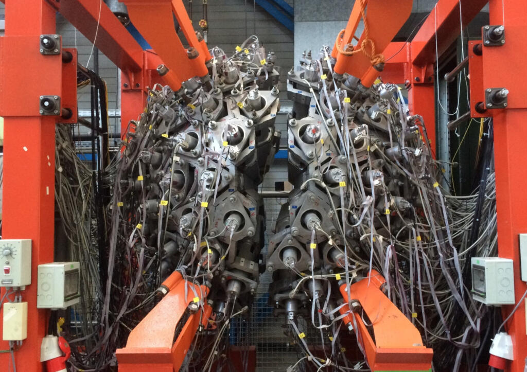
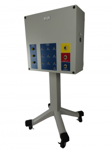
Our solution used a cRIO to measure both current and voltage from each leg of the 3-phase power (and neutral) by using appropriate cSeries modules connected to various voltage and current test points within the UPS. The cRIO had enough slots to allow a single cRIO to measure a single UPS. This cRIO and connection points were housed in a movable test stand (see image above).
Assessment of continuous operation mainly reviewed the UPS output power quality. Here, it was important to know the amplitude and phase of each leg of the 3-phase power. Synchronous data acquisition between all voltages and current channels was needed for proper timing alignment of collected data points.
Assessment of transient operation was often a review of power ripple and recovery time. For example, in the event of grid power loss, a UPS would switch over to backup power, with the result being a small transient created on the output of the UPS. Again, the voltages and currents needed to be collected synchronously to assure that event timing was aligned.
For increased power capacity, the UPSs could be connected in parallel. When ganged together, the continuous and transient behavior of each UPS needed to be compared to the others, in order to capture the behavior of the entire combined system. Consequently, each cRIO (one per UPS) had to share a clock to enable synchronous data collection across all cRIOs. A timing and synchronization module was placed into each cRIO chassis with one cRIO acting as the master clock source and the others being slaved to that clock. Several test stands were then connected together to share this clock to achieve the simultaneous sampling across all test stands.
The overall test system architecture has a master PC communicating with each cRIO. Each cRIO was placed in certain activity states by the master PC, such as “arm for measurement”, “transfer collected data”, and “respond with system health”. This arrangement enables the number of cRIO-based test stands to shrink or grow depending on the number of UPSs being testing in parallel.
Results
The test system connected the timing module in each cRIO-based test stand in a daisy-chained configuration, leading to data sampling synchronization error of less than 100 ns between all cRIOs, which translates to about +/-0.001 degree phase error for 60 Hz power signals. This timing synchronization was more than sufficient to analyze the collected waveform data for power quality and transient structure.
LabVIEW was used to create various configurable test steps that could be executed in random order as well as in an automated sequential manner. Our client was thus able to test a UPS in a predefined manner as well as react rapidly to queries from their customer when they were viewing a factory run-off test. For example, the customer might ask to re-run the same test several times in a row to validate consistent responses.
Each type of test included automated analysis routines that numerically calculated the relevant parameters against which the UPS was being checked. Not only was this automated calculation faster, but it reduced mistakes and improved reproducibility as compared to the previous post-testing partially manual calculations.
Data from all tests, even repeated ones, on a given UPS were archived for quality control purposes and made a part of the device history for that UPS.
Finally, the report generation capability built into this test system was far superior to the previous methodology by allowing our client to hand their customer a professional report package practically immediately the testing was complete. Customer satisfaction was improved substantially with this state-of-the-art test system.
Manufacturing Test – for mission-critical components

Manufacturing Test – for mission-critical components
Using PXI & LabVIEW RT
Client: A major manufacturer of implantable cardiac and neural stimulators
Challenge
Our client needed several extremely reliable test systems to test the batteries that power their implantable medical devices. These new test systems were needed for two main reasons. First, the needed to upgrade existing obsolete test equipment, based on antiquated hardware and software. Second, new battery designs could not be tested on the old equipment.
A critical aspect of the new test system was the need to detect any excessive charge being extracted from the battery, thus rendering it unsuitable for surgical implantation. Thus, the test system needed to monitor the total energy withdrawn from a battery during testing to assure that it never exceeded a certain limit while also offering precise control of the type of pulses being drained from a battery.
All test results had to be stored in a database in order to maintain device history for each battery manufactured for archiving, quality control, and process improvements.
Solution
The updated manufacturing test system is PXI-based along with a custom micro-controller-based circuit board for some low-level control. Each PXI controller communicated to the microcontroller (uC) on the custom PCB via CAN. The uC controlled the current drain from the battery while monitoring actual current and voltage from the battery at over 1000 samples per second using a precision 6.5 digit PXI DMM. Additionally, each PXI chassis was used to test many hundreds of batteries. Signal connections were handled by several switch multiplexers. Overall control of all the PXI testers was managed by a host PC connected to the PXI controller.
Benefits
- Reduced test system cost vs complete COTS solution with combo LabVIEW RT on PXI and firmware on microcontroller-based custom circuit board
- Enabled tight control of DUT operation on controller with microsecond level responsiveness while being supervised by higher-level PXI RT
- Quick-reaction test abort capability
- Test results stored to database for archiving, quality control, and process improvements
System Overview
In a simplified view, the testing proceeded by pulsing the battery with a series of different durations and varying amperages. The exact sequence of this pulsing is unique for each DUT model. Measurements were made using a PXI filled with various NI boards such as DMMs, for accuracy, and data acquisition cards, for general purpose use.
Additionally, the pulsing amperage levels needed to be tightly controlled in order to know that the tests have been performed properly. Thus, a real-time amperage control scheme had to be implemented to maintain the level requested for the pulse. We chose to accomplish this control via an analog control circuit developed using a custom Viewpoint-developed circuit board. This board was controlled via a Microchip PIC microprocessor. The LabVIEW RT application communicated with the microcontroller to setup the pulsing sequence and coordinate the start and stop of the pulsing and the NI acquisition hardware.
This custom circuitry also reduced the overall cost of the test system by about 40%.
The engineering time to design this custom circuitry was more than offset by the reduction in material costs because more than 10 test systems were deployed, allowing the non-recurring engineering effort to be shared between many systems.
When no critical issues were detected, the waveforms acquired by the PXI system were stored and then analyzed to determine the viability of the DUT. The pass/fail disposition, the waveforms, the total energy consumed, and other test results were then passed along to a host supervisory PC that managed all these results in a database for archiving, quality control, and process improvements, each set of results being tied to the unique unit serial number.
The test systems provided reliable operation for testing the large annual production volumes of the mission-critical DUTs.
Since we designed the system to interface to our customer’s host supervisory PC via ethernet-based commands, the verification and validation (V&V) process could be supported by our customer in their Installation and Operational Qualification (IQ/OQ) efforts. Specifically, they wrote the IQ/OQ procedures around software that emulated interfacing with the host supervisory PC. This approach allowed them to automate parts of the V&V thus saving them almost 1 week of effort.
| SOFTWARE FUNCTIONS |
|---|
| LabVIEW RT – for managing the microcontroller functions and overall data collection and safety monitoring |
| Microcontroller application – to provide precision pulsing of the batteries |
| Communicate to the host PC – to both receive pulsing instructions and configurations and to return pulse waveforms for each battery tested. |
| MAIN HARDWARE COMPONENTS |
|---|
| PXI chassis & controller |
| PXI DMM |
| PXI analog input modules |
| SCXI multiplexing switches |
| INTERFACES / PROTOCOLS: |
|---|
| Ethernet TCP-IP |
| CAN |
Manufacturing Test System for Electrical Components

Manufacturing Test System for Electrical Components
Replacing Obsolete Custom Electronics with cRIOs in High-Power Capacitor Testing
Modular Embedded cRIO-based Test Stands Shorten Development and Reduce Risk in Complex PC-based Test System
Client: A major manufacturer of electrical power generation and distribution equipment.
Problem Scope
This project involved retrofitting a test system used to verify operation of a high-power capacitor used in electrical power distribution. This system was originally built around 1990. Critical sections of the original test system relied on custom, wire-wrapped analog and digital circuitry to process, analyze, and isolate the high-voltage and high-current signals created by the capacitor. Analog filters, rectifiers, and comparators produced pass/fail status signals. A master PC, other measurement and control equipment, the analog circuits, and a six-position carousel were integrated to create the entire automated test and control system.
For each unit under test (UUT), test specifications are obtained from a Manufacturing Execution System (MES) and cached locally. The test stands at each carousel position are designed to run independently. This parallel capability allows greater throughput and reduced test time per capacitor unit. In addition, as different capacitor models move through the carousel stations, the test stand at each station must be aware of the particular model being tested at that station and adjust test parameters and conditions accordingly.
Test results for UUT are pushed back to the MES system for record retention and data mining. The existing MES interfaces were retained exactly for the retrofit.
Challenge
All capacitors require 100% testing prior to shipment, so the test system is critical for the facility operation. Two or even three shifts are common depending on production needs and the facility cannot afford any significant downtime. Thus, a challenge was to design and build a test system that worked and was very robust.
Another huge challenge was the lack of documentation on the existing system, requiring a sizable amount of reverse engineering to understand the test system operation before development on the new system could begin.
Furthermore, one of the most important challenges surrounded replacement of substantial amounts of original test equipment before the new test equipment could be installed. Thus, we absolutely had to minimize the time and risk in this upgrade changeover.
Technical Highlights
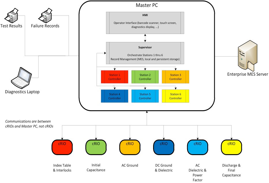
A schematic of the overall system architecture is shown in the figure. The major components of the system are:
- Master PC for supervisory control and test execution management
- NI cRIOs with FPGAs and Ethernet for test stands providing independent yet PC-supervised operation
- Station-specific FPGA code for replacing wire-wrap circuitry functionality
- Integration with existing MES, safety equipment, tooling, and measurement hardware
The architecture chosen was made very modular by the capabilities offered by the cRIO. The Master PC interfaced with station-specific measurement instrumentation as needed, such as GPIB controlled equipment, and coordinated control and outcomes from the cRIO-based test stands. This additional equipment is not shown in the figure.
Solution
The Master PC had three main functions
- Coordinating all the activities across the six cRIO-based test stands.
- Interfacing with the existing MES database and printers at the manufacturing facility.
- Providing the operator interface and, when needed, access to engineering screen on a diagnostic laptop.
The cRIO-based test stands were essential to the success of this test system. Each cRIO functioned as the equivalent of a high-speed standalone instrument.
The cRIOs at each carousel test position provided the following features:
- Digital I/O for machine feedback, safeties, and fault conditions
- State machines to coordinate with external commands and signals
- Perform numeric calculations to emulate the old analog circuitry
- Control loops for currents associated with voltages needed by different capacitors
- Communication support with the master PC
- Computation and detection of internal fault and UUT pass/fail conditions
We were able to duplicate the behavior of the wire-wrapped circuitry by converting the schematic diagrams of these circuits into FPGA code and then tweaking that code to mimicking the actual signals we measured with data acquisition equipment on the original test hardware.
The outputs of the circuitry were reconstructed on the FPGA with band-pass filtering, calibration compensation, point-to-point RMS, and phase & frequency functions. This functionality was implemented in fixed-point math and the 24-bit inputs on the A/D provided sufficient resolution and bandwidth for a faithful reproduction of the electronic circuitry. These embedded cRIOs provided a very effective solution to what otherwise might have required another set of costly and rigid custom circuits.
Finally, for optimizing the task of replacing the old equipment, we used a set of cRIOs, not shown in Figure 1, to provide Hardware-In-the-Loop (HIL) simulation of the manufacturing and measurement equipment. These cRIOs imitated the rest of the machine by providing inputs to and reacting to outputs from the embedded cRIO controllers, thus supporting comprehensive verification of the new test system before the tear-out of the existing hardware. Furthermore, these HIL cRIOs enabled fault injection for conditions that would have been difficult and possibly dangerous to create on the actual equipment.
If you’re looking for an electrical test system, reach out here to chat with us.
We’ve helped teams at some of the world’s most innovative companies