Portable Test Stands for Production Test of Large Uninterruptible Power Supplies
Manufacturing Test of UPS Units Designed for Data Center Backup Power
Client: A major manufacturer of data-critical three-phase uninterruptable power supplies
Challenge
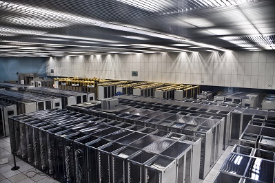
A major manufacturer of very large three-phase uninterruptible power supplies (UPSs) needed better measurement, analysis, and report generation capabilities. Their clients used these UPSs on mission critical equipment, such as data warehouse server farms, communications equipment, and so one. Existing testing procedures used equipment that did not allow for complete simultaneous coverage of all sections of a UPS unit, from input to output. Our client wanted a better understanding of the signals on each of the three phases at various locations within the UPS, especially when power sources were switched or faults were induced. The physical extent of these UPSs could be large, especially when several were combined. Having movable test stands would make access to these test locations less cumbersome.
Also, in the prior test procedure, factory acceptance reports were manually assembled for our client’s end-customers, delaying the final sign-off. Finally, since the end-customer might want to run a specially configured test or run a series of tests in a different sequence than some other end-customer, our client wanted to be able to rerun certain types of tests or run tests in a customer-specific order. Thus, the test sequencing needed to be flexible and editable, possibly on the fly.
Finally, synchronization between the data collection on all signals was critical to assess functionality, since all 3-phases of the UPS output needed to be in the proper timing relationship.
Solution
At a high-level, the majority of testing a UPS relies on knowing the reaction of the UPS to changes on the input side (such as a grid power outage) and changes on the output side (such as an immediate heavy load). Thus, many of the tests performed on a UPS deal with power quality measurements, such as defined by IEEE 519 or IEC 61000 series standards, which cover both continuous and transient operation. The StepWise test execution platform was utilized to allow the customer to develop arbitrary test sequences using the application specific test steps developed for the program.
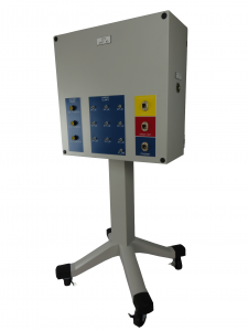
Our solution used a cRIO to measure both current and voltage from each leg of the 3-phase power (and neutral) by using appropriate cSeries modules connected to various voltage and current test points within the UPS. The cRIO had enough slots to allow a single cRIO to measure a single UPS. This cRIO and connection points were housed in a movable test stand (see image above).
Assessment of continuous operation mainly reviewed the UPS output power quality. Here, it was important to know the amplitude and phase of each leg of the 3-phase power. Synchronous data acquisition between all voltages and current channels was needed for proper timing alignment of collected data points.
Assessment of transient operation was often a review of power ripple and recovery time. For example, in the event of grid power loss, a UPS would switch over to backup power, with the result being a small transient created on the output of the UPS. Again, the voltages and currents needed to be collected synchronously to assure that event timing was aligned.
For increased power capacity, the UPSs could be connected in parallel. When ganged together, the continuous and transient behavior of each UPS needed to be compared to the others, in order to capture the behavior of the entire combined system. Consequently, each cRIO (one per UPS) had to share a clock to enable synchronous data collection across all cRIOs. A timing and synchronization module was placed into each cRIO chassis with one cRIO acting as the master clock source and the others being slaved to that clock. Several test stands were then connected together to share this clock to achieve the simultaneous sampling across all test stands.
The overall test system architecture has a master PC communicating with each cRIO. Each cRIO was placed in certain activity states by the master PC, such as “arm for measurement”, “transfer collected data”, and “respond with system health”. This arrangement enables the number of cRIO-based test stands to shrink or grow depending on the number of UPSs being testing in parallel.
Results
The test system connected the timing module in each cRIO-based test stand in a daisy-chained configuration, leading to data sampling synchronization error of less than 100 ns between all cRIOs, which translates to about +/-0.001 degree phase error for 60 Hz power signals. This timing synchronization was more than sufficient to analyze the collected waveform data for power quality and transient structure.
LabVIEW was used to create various configurable test steps that could be executed in random order as well as in an automated sequential manner. Our client was thus able to test a UPS in a predefined manner as well as react rapidly to queries from their customer when they were viewing a factory run-off test. For example, the customer might ask to re-run the same test several times in a row to validate consistent responses.
Each type of test included automated analysis routines that numerically calculated the relevant parameters against which the UPS was being checked. Not only was this automated calculation faster, but it reduced mistakes and improved reproducibility as compared to the previous post-testing partially manual calculations.
Data from all tests, even repeated ones, on a given UPS were archived for quality control purposes and made a part of the device history for that UPS.
Finally, the report generation capability built into this test system was far superior to the previous methodology by allowing our client to hand their customer a professional report package practically immediately the testing was complete. Customer satisfaction was improved substantially with this state-of-the-art test system.