HIL Test System Developers
HIL & SIL with LabVIEW & NI hardware
How we can help
Capabilities & Expertise
HIL / SIL Case Studies
Custom FlexRIO Adaptor Module supports HIL Test Upgrade
Custom FlexRIO Adaptor Module supports HIL Test Upgrade
A custom-COTS approach reduces cost and delivery time.
Client – Major National Research Lab

Challenge
Our client has a client (the end-user) for which they developed an HIL test system several years prior. Parts were obsolete and the system needed an upgrade. The prior system had many custom-designed electronic components which could not be replaced without a complete redesign.
Consequently, our client wanted to use COTS. However, one device needed 28 VDC digital I/O, a couple of lines which carried significant current (amp, not milliamp, levels) and at switching rates much higher than a COTS solid state relay could provide.
Solution
Viewpoint reviewed the requirements and created a hybrid COTS-custom solution. We combined an NI FlexRIO module with a custom FlexRIO Adapter Module (FAM) for the front end to satisfy the 28 VDC signals levels and required current drive.
Benefits
- COTS FlexRIO integrates into the remainder of our client’s PXI-based test system.
- The Custom I/O was designed for flexibility. Our client can use this FAM for both their initial end-user and other programs / clients too.
- Reduced cost relative to a completely custom solution.
- Delivery time reduced by months relative to a custom solution
FAM Overview
The custom FAM interfaced with the NI FlexRIO module, which offered low-level digital I/O (3.3 V logic), to digital signal conditioning hardware that provided the 28 VDC signal levels and required current drive.
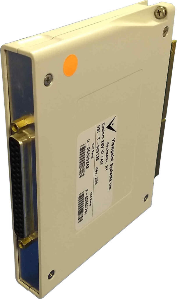
Each I/O pin was configurable as input or output (source or sink). Each bank of 4 channels had an adjustable threshold level set via an adjustable DAC output. Some of the channels are designed for amp-level current drive, while the remainder were 250 mA. All I/O was fused appropriately.
Viewpoint also developed LabVIEW FPGA and VHDL to enable our client and the end-user to:
- Configure the I/O as in or out.
- Communicate to the DAC to allow custom input threshold trigger levels.
- Read and write the digital data.
| SOFTWARE FUNCTIONS |
|---|
| Set the direction of each of the DIO channels |
| Set the threshold level on the input channels |
| Read / Write DIO Data |
| End User Application |
| HARDWARE UTILIZED |
|---|
| COTS NI FlexRIO |
| Custom FlexRIO Adaptor Module(FAM) |
| INTERFACES / PROTOCOLS |
|---|
| Customized VHDL Component Level Intellectual Property (CLIP) integrated with LabVIEW FPGA |
| LabVIEW FPGA as required along with LabVIEW and TestStand |
High-Speed Digital Subsystem Emulator
High-Speed Digital Subsystem Emulator
Client: A large company involved in C4ISR
At maximum throughput, the AEDIS systems needed to consume and produce more than about 800 MB/s/slot.
Background
A large company involved in C4ISR was developing a system for a new high-speed digital sensor device. Viewpoint was contracted to build a test system used in design validation and ultimately endurance testing of the sensor. Since the sensor was a component of a larger system which was being developed at the same time, another test system was created to simulate the sensor by feeding signals into the system. This ability to use HIL testing for both the sensor and the downstream sensor electronics enabled parallel development, thus saving time and reducing schedule.
Challenge
Both the amount of data and the frequencies of the various digital signals were nearly at the limit of hardware capabilities. At maximum throughput, the systems needed to consume during record and produce during playback about 800 MB/s/slot. The FPGA clock on the FlexRIO had to run up to 300 MHz. The skew between triggers for data transmission needed to be less than 5 ns even between multiple FlexRIO cards even when the parallel data paths have inherent skews associated with the sensor. Finally, the systems needed to handle clocks that might be out-of-phase.
Achieving these requirements required significant engineering design in the face of multiple possible roadblocks, any one of which could have eliminated a successful outcome.
Furthermore, as usual, the development timeline was tight. In this case, it was a very tight 3 months. Basing the solution on our AEDIS platform was critical to meeting this challenge.
Viewpoint’s Solution
To meet the timeline, we had to work in parallel across several fronts:
- LabVIEW-based application development for both record and playback
- LabVIEW FPGA development for marshalling data between the controller and DRAM
- Custom FAM circuit board design and build
- FlexRIO FPGA CLIP nodes and code for low-level data handling
Technical Highlights
This sensor had several parallel data paths of clock and data lines with clock speeds up to 300 MHz on each path requiring exacting design and build of a custom FlexRIO Adapter Module (FAM) and unique custom CLIP nodes for extending the FlexRIO FPGA capabilities. The FAM also had a special connector for interfacing to the customer’s hardware.
Additional NI hardware and software completed the system components.
Results
The choice to base the AEDIS emulators on NI hardware and software was critical to completing this project. The open architecture in both hardware (custom FAM) and software (CLIP Nodes) enabled us to include some very creative extensions to the base toolset without which the project would not have succeeded in the allotted pressured schedule and on a predetermined budget. We were able to stretch the capabilities of the hardware and software very close to their maximum specifications by combining COTS and custom much more cost effectively than a purely custom design. Further, with HIL tests, both the sensor and the sensor electronics could be developed in parallel, leading to a significant schedule buyback for our client.
LabVIEW Layers
The host application, written in LabVIEW, managed the configuration of the data acquisition and the control of the LabVIEW RT-based FlexRIO systems. The configuration primarily dealt with the number of sensor channels in use, skew settings between digital lines, and other parameters that dealt with the organization of the data passed between the sensor and the FlexRIO.
Two FlexRIO applications were written, one for record and one for playback. Each FlexRIO application was written in LabVIEW, and managed the configuration of the FlexRIO cards and the movement of data between the FlexRIO cards and the RAID drives. Note that Windows supported for the RAID driver. Between 10 and 32 DMA channels were used for streaming, depending on the number of sensor channels being used.
And, each FlexRIO application had an FPGA layer, written in LabVIEW FPGA enhanced with custom CLIP nodes. For the record application, we developed a custom DRAM FIFO on the FPGA to assist with the latencies on the PXIe bus. For the playback application, we were able to stream directly from DRAM.
FlexRIO Considerations
The FlexRIO and stock FAMs from NI were initially considered as candidates for this project. Clearly, working with commercial-off-the-shelf (COTS) components would be most effective. Three options were available at the project start which could accommodate the required clock frequencies, but none offered both the required channel counts and skew/routing limitations. Hence, we had to design a custom FAM. This decision, made before the start of the project, turned out to be wise in hindsight because the parallel development path resulted in some shifts of sensor requirements which could be accommodated with the custom FAM but might have led to a dead-end with a COTS FAM.
FlexRIO CLIP
In LabVIEW FPGA, a CLIP Node is a method to import custom FPGA IP (i.e., code) into a LabVIEW FPGA application. CLIP stands for Component-Level Intellectual Property. We needed to use special Socketed CLIP Nodes (i.e., VHDL that can access FPGA pins) for this project because we could expose additional features of the Xilinx Virtex-5 not exposed in LabVIEW FPGA by accessing Xilinx primitives. Some specific features were:
- Faster FPGA clocking
- Additional clocking options
- Individual clock and skew control
- Custom PLL de-jitter nodes
Essentially, the FPGA design had a majority of FPGA code developed in LabVIEW FPGA and we used CLIP Nodes for interfacing the signals between the FlexRIO and the FAM.
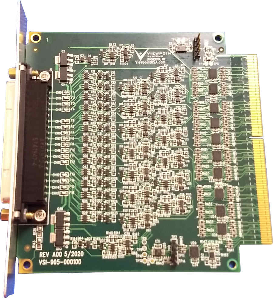
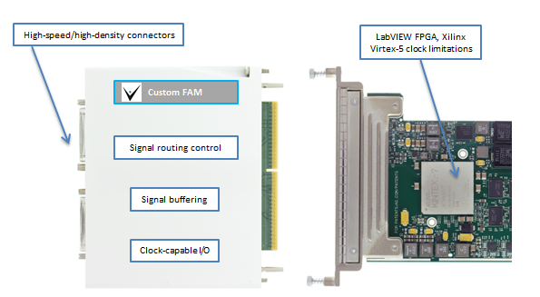
FlexRIO Adapter Module
As mentioned earlier, we had to create a custom FAM because of the need to route high speed signals from customer-specific high density connectors while synchronizing signals across multiple data channels and FPGA modules to within one (300 MHz) clock cycle.
At these high-speeds, the FAM needed careful buffering and impedance matching both on the signals as well internal components on the FAM PCB. At the start of the design, we utilized Mentor Graphics HyperLynx High Speed DDR signaling Simulation software to minimize signal reflections prior to building actual hardware. This step saved countless hours in spinning physical hardware designs.
We designed the FAM to allow channel routing and access to additional clock and trigger pins on the Xilinx chip and PXIe backplane.
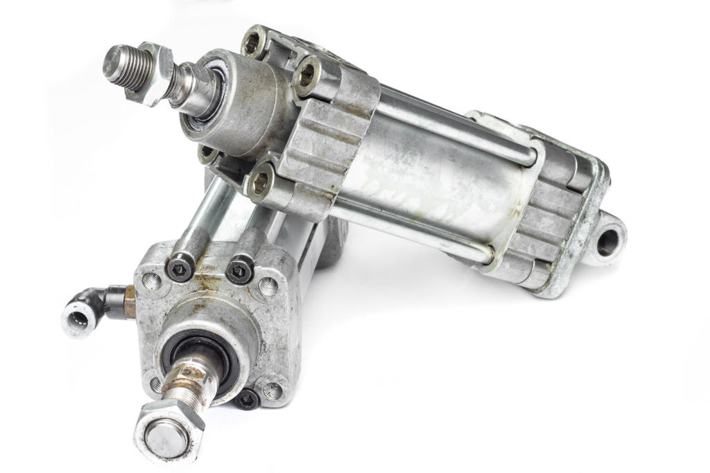
Product Validation using LabVIEW RT & LabVIEW FPGA – Electromechanical Actuator Test Stand
Product Validation using LabVIEW RT & LabVIEW FPGA – An electromechanical test stand for an aerospace actuator
Automated testing reduces operator man hours and increases production throughput.
Client – A manufacturer of actuators in the mil-aero industry.
Challenge
New Product Introduction (in this case a new controller and new actuators) drove the need for a new aerospace electromechanical test stand.
Solution
New NI PXI-based electromechanical test equipment provided automated HIL testing, report generation, and SPC data generation. The sequencing of the test procedure, reporting, and verifiable results were managed with the StepWise test executive platform.

Benefits
- Automated testing reduces operator man hours and increases production throughput.
- Meets strict customer requirements regarding testing and data recording in a verifiable manner.
- Automated Test Report Generation.
- Collects data to support SPC (Statistical Process Control).
- Ability to interact with the internal state of the controller FPGA via the LVDS communication link.
System Overview
Viewpoint developed the software and selected NI data acquisition and control hardware for the test stand. There are several layers of software functionality. Also, the modularity of the test stand hardware assures maintainability for future upgrades and reduction of potential obsolescence issues, especially since the “programmability” of the FPGA-based HW allows repurposing via LabVIEW FPGA.
| HOST LABVIEW SOFTWARE LAYER |
|---|
| Test sequencer |
| Test steps (e.g. Frequency Response, Step Response, Dynamic Stiffness, Fault Response, Power Consumption) |
| Test Report Generator |
| GUI |
| REAL-TIME (RT) LABVIEW SOFTWARE LAYER |
|---|
| Data acquisition |
| 1553 comms |
| Function generator |
| Error detection |
| ESTOP |
| LABVIEW FPGA SOFTWARE LAYER |
|---|
| Synch data from 3 sources (tester, UUT, external DAQ device) |
| Stream high-speed data to disk |
| Stream high-speed data to analog outputs for HIL test |
| Custom communication protocol used by UUT over LVDS lines |
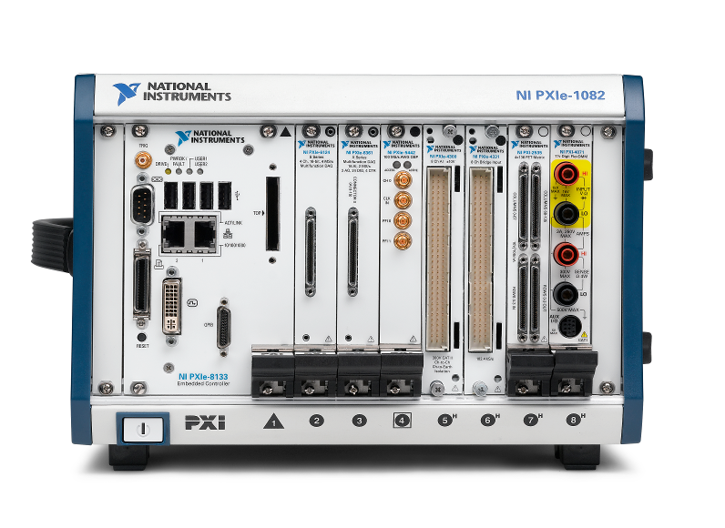
| HARDWARE RECOMMENDED |
|---|
| NI PXIe |
| NI FlexRIO card with LVDS adapter module |
| Multiple NI R Series cards |
| High speed, high voltage, isolated analog input cards |
| INTERFACES / PROTOCOLS |
|---|
| MIL-STD 1553 bus |
| LVDS |
| Ethernet |
| Custom TCP/IP |
*- images are conceptual only, not actual
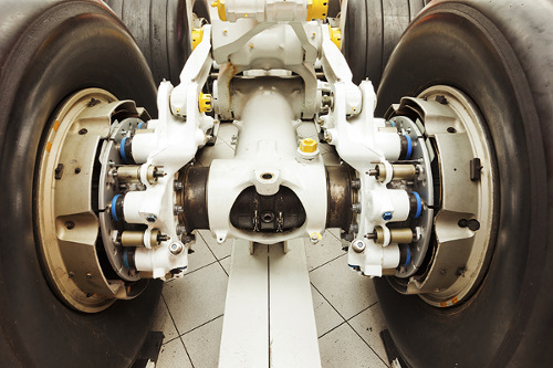
Decreasing Test Time for Aircraft Landing Gear

Decreasing Test Time for Aircraft Landing Gear
Endurance Testing for Aircraft Nose Landing Gear Steering
Client: A major manufacturer of aircraft landing systems
Challenge
A major manufacturer of aircraft landing equipment needed to develop a means of endurance and fatigue testing new designs for aircraft steering. The actuators involved in steering the nose landing gear (NLG) required precise and reliable control through thousands of steering cycles.
Control loops needed to be closed at faster than 1 ms.
Prior systems were handled manually without real-time control and monitoring.
Solution
Our customer designed and built a test rig to provide the hydraulics and environmental conditions for the endurance testing on the NLG. Viewpoint Systems supplied the electronic data acquisition and control hardware coupled with real-time software to provide the required fast control loops. The configuration and execution of the 1000s of steering cycles were managed by the same data acquisition and control system through a set of configuration screens that allowed specification of turn rates, min/max angles, drive and resistive torque settings, and so on. The flexibility offered with this HIL test capability mimicked the variety of conditions that the NLG would encounter in actual use.
- The various PID control loop configurations were also configurable along with gain scheduling required under different operating conditions.
- The environmental conditions were supported by controlling a temperature chamber through ramp and soak settings occurring during the steering tests.
- Measurements on the steering performance were collected from commanded setpoints, sensor readings, and controller outputs during the entire test run.
- Alarm and fault conditions, such as force exceedance, were monitored continuously during operation so that the system could safely run unattended.
Since the deployed solution was an aerospace test system, the entire system underwent an extremely rigorous acceptance testing procedure to verify proper and safe operation.
| SOFTWARE FUNCTIONS |
|---|
| Arbitrary Load and Position Profiles |
| Flight Position Control |
| Load Position/Force Control |
| Endurance/Flight Schedule Execution |
| Deterministic RT for DAQ and PID Control |
| HARDWARE |
|---|
| PXI/SCXI Hybrid RT Chassis |
| Discrete Pump Skid Interface |
| Custom Control Panel/Console |
| INTERFACES |
|---|
| Ethernet TCP/IP |
| SCXI |
Results
Prior to deployment of our system, setup of a test was much more manual and operators needed to be around to monitor operation.
With our new system, complete endurance testing could be specified and executed with minimal supervision. Furthermore, the tight integration of real-time control, HIL testing, and coordinated data collection made report creation much simpler than before.
The rigorous acceptance test gave trustworthiness to the data and allowed the design engineers to validate performance more quickly than the prior semi-automatic and manual methods of operation.
Setup of tests has been improved from prior operations. The endurance testing itself operated over a huge number of cycles lasting weeks to months between scheduled lubrication and maintenance.
The deployed system measures performance during the entire testing, even between the scheduled downtime.
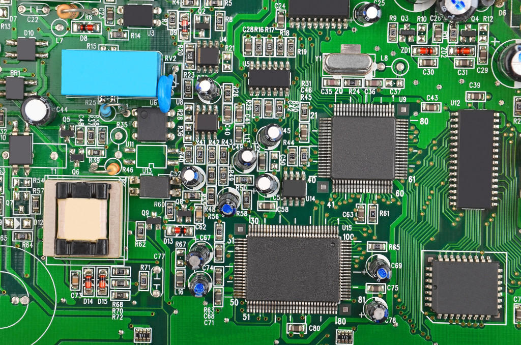
Manufacturing Test System for Electrical Components

Manufacturing Test System for Electrical Components
Replacing Obsolete Custom Electronics with cRIOs in High-Power Capacitor Testing
Modular Embedded cRIO-based Test Stands Shorten Development and Reduce Risk in Complex PC-based Test System
Client: A major manufacturer of electrical power generation and distribution equipment.
Problem Scope
This project involved retrofitting a test system used to verify operation of a high-power capacitor used in electrical power distribution. This system was originally built around 1990. Critical sections of the original test system relied on custom, wire-wrapped analog and digital circuitry to process, analyze, and isolate the high-voltage and high-current signals created by the capacitor. Analog filters, rectifiers, and comparators produced pass/fail status signals. A master PC, other measurement and control equipment, the analog circuits, and a six-position carousel were integrated to create the entire automated test and control system.
For each unit under test (UUT), test specifications are obtained from a Manufacturing Execution System (MES) and cached locally. The test stands at each carousel position are designed to run independently. This parallel capability allows greater throughput and reduced test time per capacitor unit. In addition, as different capacitor models move through the carousel stations, the test stand at each station must be aware of the particular model being tested at that station and adjust test parameters and conditions accordingly.
Test results for UUT are pushed back to the MES system for record retention and data mining. The existing MES interfaces were retained exactly for the retrofit.
Challenge
All capacitors require 100% testing prior to shipment, so the test system is critical for the facility operation. Two or even three shifts are common depending on production needs and the facility cannot afford any significant downtime. Thus, a challenge was to design and build a test system that worked and was very robust.
Another huge challenge was the lack of documentation on the existing system, requiring a sizable amount of reverse engineering to understand the test system operation before development on the new system could begin.
Furthermore, one of the most important challenges surrounded replacement of substantial amounts of original test equipment before the new test equipment could be installed. Thus, we absolutely had to minimize the time and risk in this upgrade changeover.
Technical Highlights
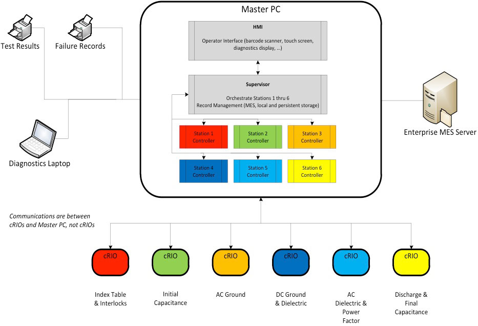
A schematic of the overall system architecture is shown in the figure. The major components of the system are:
- Master PC for supervisory control and test execution management
- NI cRIOs with FPGAs and Ethernet for test stands providing independent yet PC-supervised operation
- Station-specific FPGA code for replacing wire-wrap circuitry functionality
- Integration with existing MES, safety equipment, tooling, and measurement hardware
The architecture chosen was made very modular by the capabilities offered by the cRIO. The Master PC interfaced with station-specific measurement instrumentation as needed, such as GPIB controlled equipment, and coordinated control and outcomes from the cRIO-based test stands. This additional equipment is not shown in the figure.
Solution
The Master PC had three main functions
- Coordinating all the activities across the six cRIO-based test stands.
- Interfacing with the existing MES database and printers at the manufacturing facility.
- Providing the operator interface and, when needed, access to engineering screen on a diagnostic laptop.
The cRIO-based test stands were essential to the success of this test system. Each cRIO functioned as the equivalent of a high-speed standalone instrument.
The cRIOs at each carousel test position provided the following features:
- Digital I/O for machine feedback, safeties, and fault conditions
- State machines to coordinate with external commands and signals
- Perform numeric calculations to emulate the old analog circuitry
- Control loops for currents associated with voltages needed by different capacitors
- Communication support with the master PC
- Computation and detection of internal fault and UUT pass/fail conditions
We were able to duplicate the behavior of the wire-wrapped circuitry by converting the schematic diagrams of these circuits into FPGA code and then tweaking that code to mimicking the actual signals we measured with data acquisition equipment on the original test hardware.
The outputs of the circuitry were reconstructed on the FPGA with band-pass filtering, calibration compensation, point-to-point RMS, and phase & frequency functions. This functionality was implemented in fixed-point math and the 24-bit inputs on the A/D provided sufficient resolution and bandwidth for a faithful reproduction of the electronic circuitry. These embedded cRIOs provided a very effective solution to what otherwise might have required another set of costly and rigid custom circuits.
Finally, for optimizing the task of replacing the old equipment, we used a set of cRIOs, not shown in Figure 1, to provide Hardware-In-the-Loop (HIL) simulation of the manufacturing and measurement equipment. These cRIOs imitated the rest of the machine by providing inputs to and reacting to outputs from the embedded cRIO controllers, thus supporting comprehensive verification of the new test system before the tear-out of the existing hardware. Furthermore, these HIL cRIOs enabled fault injection for conditions that would have been difficult and possibly dangerous to create on the actual equipment.
Trying to select test hardware but overwhelmed by NI’s massive catalog of hardware options? Whether you’ve got a BOM started and are looking for confirmation that you’re on the right path, or you’re not even sure where to begin, check out our NI Hardware Selection Services for help.
We’ve helped teams at some of the world’s most innovative companies