Test System Development for the Medical Device industry
Custom Medical Device Test System Development for:
How we can help: our capabilities & expertise
Want more proof points? Check out these medical device test case studies:
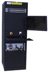
Automated Measurement System – Verifying Flow Rate Performance in a Medical Device
Automated Measurement System – Verifying Flow Rate Performance in a Medical Device
Assessing quality and managing traceability of a medical device
Automation increases throughput by testing multiple units independently
Client
Worldwide supplier of products for surgery
Challenge
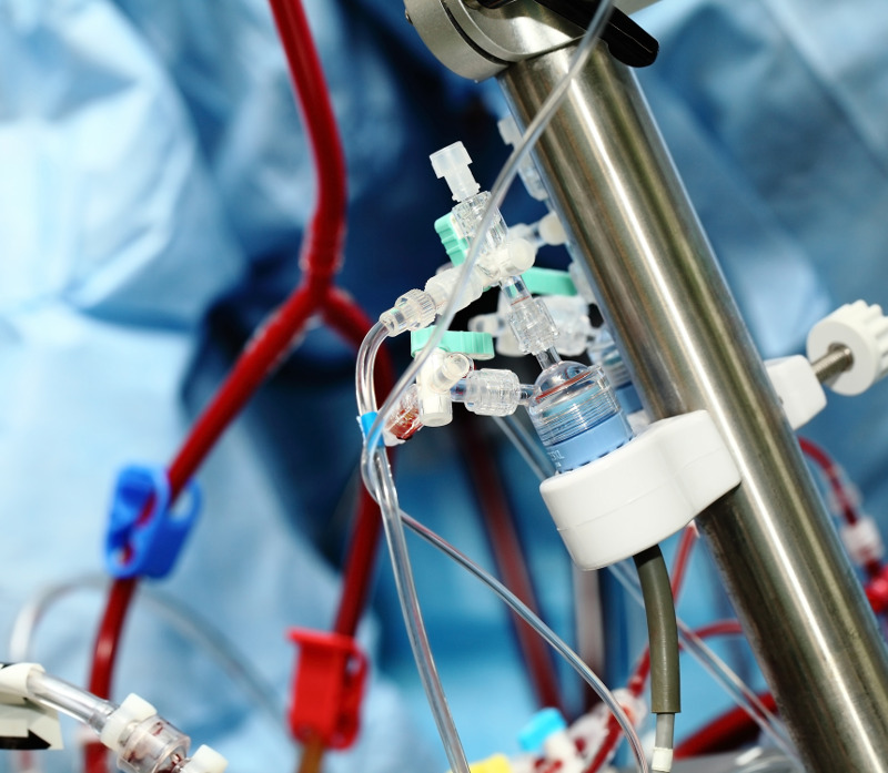
Our client wanted to perform detailed quality checks on the performance of some of their fluid dispensing products. These products dispense fluid over long periods of time (hours) so rigorous testing of each unit in production would take too long. But, being medical devices, these products need to follow ISO 28620 standards and FDA 21 CFR Part 820 regulations, so a rigorous test process is helpful to fulfill these needs. The automated test system below is part of that overall fulfilment.
The client came to Viewpoint with the following high-level desires for a system to test the product:
- Support independent configuration and testing for up to 6 units.
- Simplify overall test setup by copying the configuration from one unit to another.
- Handle different volume amounts supported by assorted models.
- Measure from each unit the weight of fluid dispensed as a function of time. (Weight was converted to volume using the fluid density.)
- Compute the “instantaneous” flow rate (volume vs time) as the test progresses.
- Keep track of the calibration status of the weight scales at each of the 6 positions in the test system.
- Enable some measurements to be excluded at the start and end of the run for calculations of average flow rate.
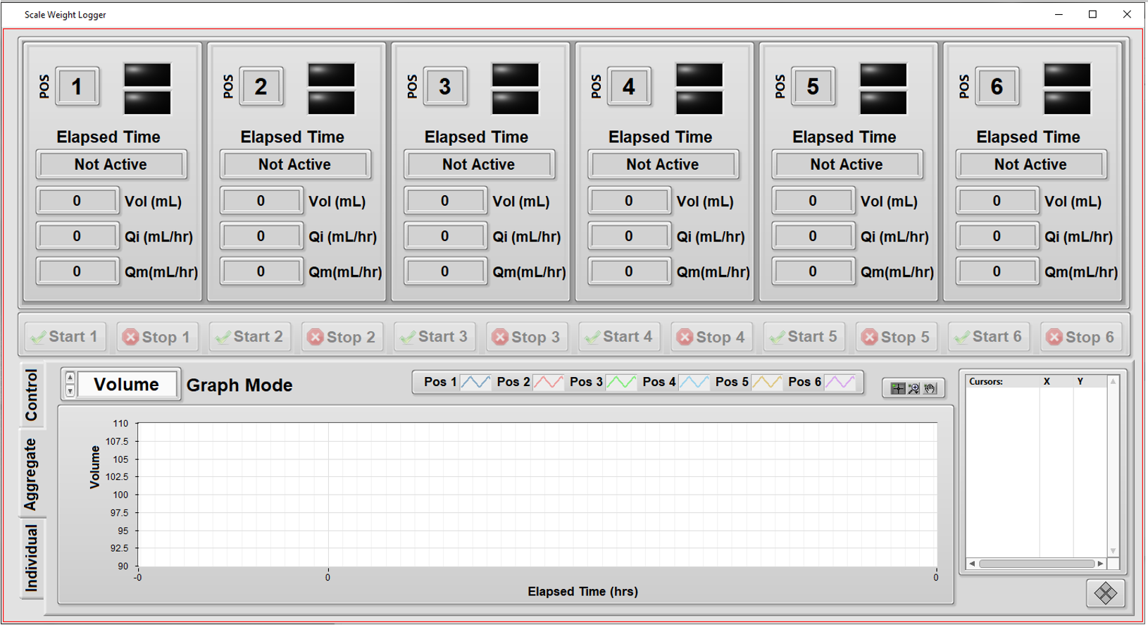
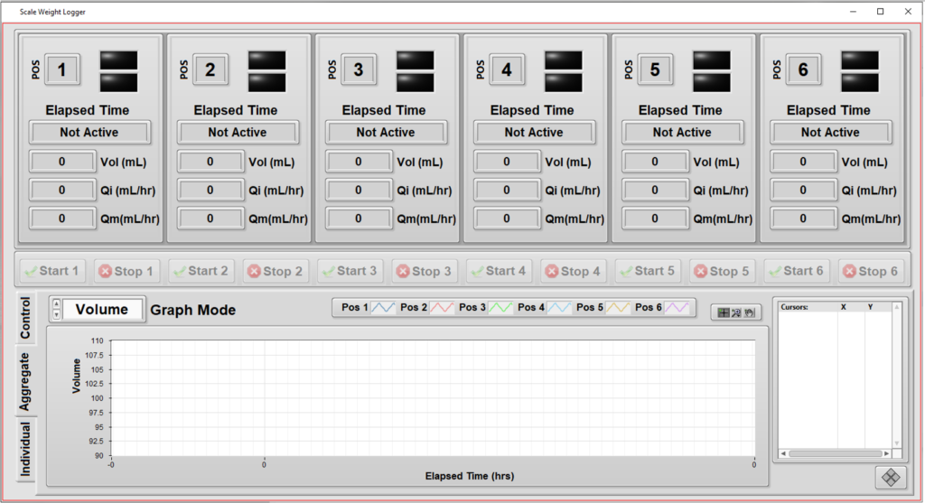
- Provide graphs and metrics of results to enable faster review of the data during the test.
- Add ability to comment on each unit while testing is in progress, and after, and track these for compliance.
- Print (PDF) a report on each unit’s results along with its identifying info, such as subcomponent lot numbers, the test datetime stamp, and the operator’s ID.
Solution
The client had an initial version of the testing application which they developed for testing their various initial design iterations. Viewpoint enhanced this existing application with the features listed above. The motivations for this enhancement were to:
- Automate testing of the initial production units more thoroughly than the existing application allowed.
- Enhance the user experience for easier testing.
A major aspect of the user experience was to support testing of multiple units independently from each other so that unit testing on one device could start/stop while other devices were installed in (or removed from) the tester without interrupting tests on other units.
- This need was especially important since some models might take twice as long to test as other models or the setup of one unit might need additional adjustments before starting. This meant that starting and stopping all at the same time could reduce utilization of the tester, and it made sense to have independent and parallel operation.
- Furthermore, with parallel testing, the tester was not constrained to having a full set of units to begin testing operation, since the tester could run with only 1 unit installed.
The other major enhancements focused on the user experience by offering real-time data of a particular unit’s testing, as well as real-time graphs to show progress. These graphs were useful because the operator could clearly see when a unit was not performing as expected and the test for that unit could be aborted without affecting testing on the other units.
Since this testing needs to follow the requirements in the ISO 28620 standard and 21 CFR Part 820, it was important for the application to be aware of the calibration status of each of the 6 weight scales, one for each position in the test system.
Benefits
The main goal of this project was to augment the test operator’s ability to set up the testing of products while providing real-time visual feedback to the operator about the testing status.
Some of the benefits of this automated test system were:
- The test automation provided consistency resulting from the software-enforced test process.
- Test status via the visual feedback helped increase the efficiency of the operator.
- Enhance the user experience for easier testing.
System Overview
The application was developed in LabVIEW and measurements were made via RS-232 communications to each of the 6 weight scales. Once a unit was installed in the tester and the operator started the test on that unit, the application:
- tared that unit’s scale,
- started the flow,
- and collected weight measurements frequently to build a curve of “instantaneous” flow versus time.
These “instantaneous” flow numbers were used to compute statistics such as maximum flow and average flow over the course of the entire test run.
Some of the primary functionality of this system includes:
- Independent tests: testing a specific unit doesn’t interfere with testing of others.
- Graphs of flow rate during the test execution: visualize the unit’s performance during the hours-long test time, not just at the end.
- Calibration check: the next calibration date of each of the weight scales are maintained in a configuration file, so the operator can check that the test system is ready to run a test at a particular position.
- Different volumes: since each unit is tested independently, the system can handle different volumes for each position in the tester.
- Enhanced commenting: operators can enter comments about each unit (or all of them) and have these comments archived for compliance purposes.
| SOFTWARE FUNCTIONS |
|---|
| Logging of weight versus time for up to 6 test positions via RS-232 communications to scales. |
| Manage the configuration and commenting of the test. |
| Save, recall, and copy configuration information to ease the operator’s setup effort and time. |
| Display graphically the curves of flow versus time while the test progresses. |
| Compute statistics on the flow after test completion. |
| HARDWARE USED |
|---|
| Multiport ethernet to RS-232 serial communications. |
Custom Endurance Test System – for a medical device
Custom Endurance Test System – for a medical device
Increased level of automation allows for multi-day and multi-week test runs
Client
A medical device manufacturer
Challenge
Our client wanted to improve the endurance testing of an implantable medical device product to help determine the recommended lifetime of the product. An obsolete test system existed, but the client wanted improved performance, UX and configurability. They wanted to just hit the “go” button and let it run for days or weeks. They also needed to be able to have new features added after the first release.
Solution
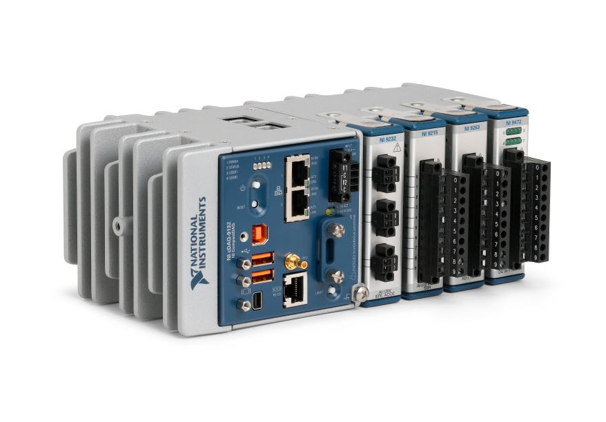
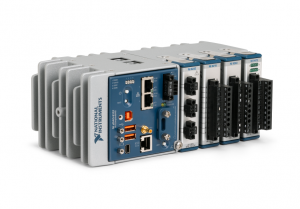
The custom product validation endurance test system utilizes NI cDAQ off-the-shelf hardware combined with custom LabVIEW-based software to provide automated N-up endurance testing of the UUT. The specific NI hardware selection was driven by both capabilities and physical space requirements. We suggested cDAQ to our client because of its small physical footprint (we connected it to a somewhat remote PC) and ability to expand into other future endurance testing needs by swapping out modules as needed.
Benefits
- Higher fidelity DAQ
- Increased configurability of the system to run tests the way the client wants to
- Increased level of automation allows for multi-day and multi-week test runs.
System Overview
The endurance tester physically stresses the UUT to measure force and eventually breakage events. These events are used to help determine the recommended lifetime of the product. The tester tests multiple UUTs in parallel in order to gather more data faster for statistical validity. The system collects data until all UUTs break or the operator stops the test.
Viewpoint provided the software and advised DAQ hardware selection. The rest of the test system hardware was selected and assembled by the client.
The automated test system applies a varying cyclical force to multiple UUTs while measuring the force applied to the device. The software automates the data acquisition, analysis, load application, and motor during a test. The system measures all forces applied simultaneously while synchronizing that data to a cycle counter. That data is analyzed to determine average, maximum, and minimum force applied to the device over a user configurable number of cycles.
While running there are multiple alarm states that are monitored. When these alarm states occur, a file can be generated to dump a user configurable duration of force measurements to a file. Other alarms generated trigger the system to change a digital output state triggering a text message to be sent to the operators of the system. The system was designed to test for weeks at a time.
| SOFTWARE FUNCTIONS |
|---|
| Test Sequencer |
| UI |
| Data Logging |
| Report Generation |
| Breakage Event Detection |
| HARDWARE USED |
|---|
| NI cDAQ |
| Multiple NI load cell cSeries modules |
| NI cSeries Digital Input module |
| NI cSeries Digital Output module |
Custom Test System Using NI PXI for Electrical Test
Custom Test System Using NI PXI for Electrical Test
Updating an obsolete tester that maintains functionality
Client – Medical Device Manufacturer
Challenge
Our client already had a test system in place, but the tester (really two test systems testing two different product variants) was becoming obsolete. The tester was old, hardware was failing, and it was getting harder and harder to keep it reliably running. They wanted a new tester to improve reliability, but maintain the functionality of the existing tester to keep the FDA-mandated verification and validation time to a minimum.
Solution
The updated end-of-line manufacturing test system maintains the functionality of the old test systems, but with updated hardware and software. The same software is utilized for both the manual test system update and the automated test system update. Our client deployed 6 manual testers and 1 automated tester.
Benefits
- Improved maintainability and reliability with updated hardware and software
- Maintains existing test system functionality to keep certification time down
System Overview
There were two variants of the new test system. One was for an older product line that utilized manual test, with an operator that connected/disconnected the UUT, and initiated the test. The other was an automated tester, integrated into a manufacturing machine. Both testers utilized custom fixtures (provided by the client), off-the-shelf NI measurement hardware (selected by Viewpoint), and custom test software (developed by Viewpoint). The software is configurable for both the manual test system and the automated test system.
| SOFTWARE FUNCTIONS |
|---|
| Read UUT limits from config file |
| Perform tester self-test |
| Measure impedance |
| Power UUT |
| Pressurize UUT |
| Measure UUT output |
| Perform leak down pressure test |
| PLC interface (for automated tester) for start, done, pass, fail |
| HARDWARE USED |
|---|
| Custom test fixture (provided by client) |
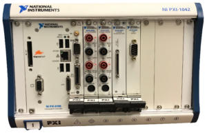
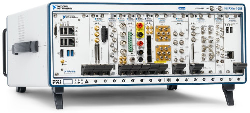
| NI PXI |
| PXI Multifunction I/O Module |
| PXI Digital I/O Module |
| PXI Relay Module |
| PXI Digital Multimeter Module |
| PXI Switch Matrix Module |
*- images are conceptual, not actual
Automated Manufacturing Test System for Electronic Medical Devices
Automated Manufacturing Test System for Electronic Medical Devices
Using PXI and LabVIEW for modular testing of over 1,000 different models
Client – a medical device manufacturer and repair depot
Challenge
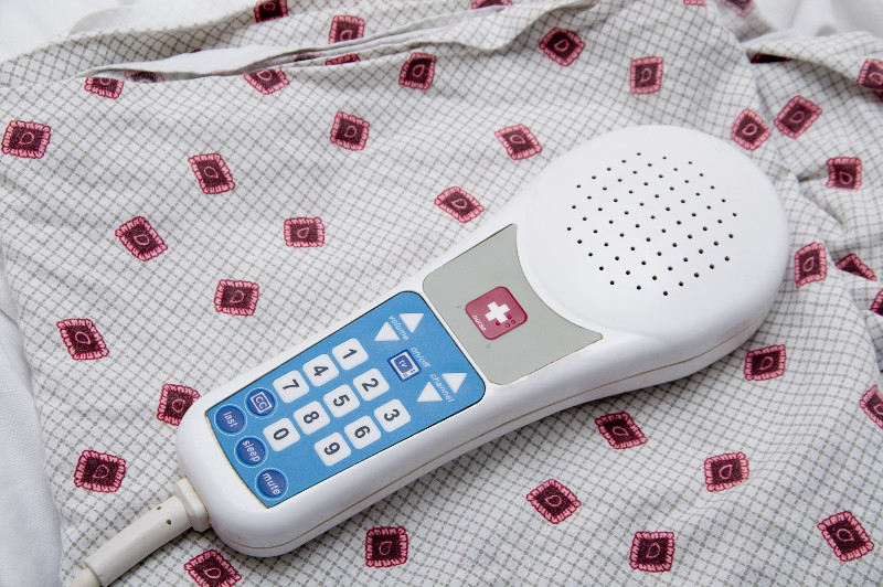
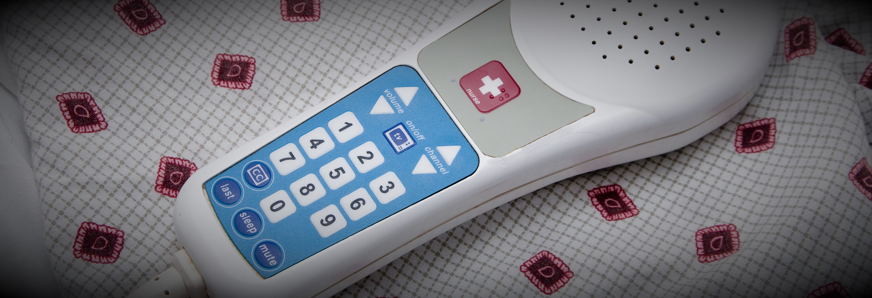
Our client manufactures hospital patient pendants used to control bed frame, nurse calling, and TV functions. The company was also growing after adapting a business model of being a repair depot for older designs for their own and the pendants of other manufacturers. As such, their products are very high mix and medium volume.
The basic functions for all these pendant models are closely related, so the client wanted a means to build a single automated test system that could verify functionality for 1000s of models. And, since the products are medical devices, the testers needed to comply to 21 CFR Part 820 and Part 11.
Solution
The testers were designed to support the common measurements needed to test the circuitry of the devices as well as the complex signals required to drive TVs and entertainment systems. A test sequence editor was created which allowed the client to create as many test sequences as needed to test each specific pendant model by creating a list from pre-defined basic measurement steps configured for each specific measurement.
For example, each device had a power supply, the voltage of which needed to be tested. To test a specific model, a voltage measurement step was added to the model-specific sequence and configured with the upper and lower measurement limits for the power supply. The complete test sequence was created by adding and configuring other measurements test steps as needed. Each test step could also be configured with switch configurations to connect the measurement equipment, such as a DMM, to the proper pins on the device circuit board.
Using this configuration process, the client was able to support the testing of well over 1000 models without any programming. A separate application was developed to create these test sequences which were saved as XML and fed to the test system for selection and execution.
The test execution was managed by NI TestStand and the pre-defined common test steps were written in LabVIEW. The test sequences and test results were interfaced to the client SQL database which they used in their ERP system. This ERP system used the results produced by the test system to help manage the workflow of production, for example by assuring that all units had passed testing before being shipped. Part 11 compliance was handled through checksums used to check if results had been modified.
Benefits
- Test sequence editor used to develop and maintain tests for 1000s of device models
- Enabling our client to create test sequences without programming reduced overall development costs by about 50%.
- Test sequences and test results were stored in the client’s ERP SQL-compliant database for integration with manufacturing workflow
- Modular and common software developed for the test systems reduced the V&V effort during IQ & OQ by allowing testing of the test execution application separate from the individual test sequences.
System Overview
The automated test system was able to execute each test sequence in three different modes: engineering, service, and production. Each mode has been specifically designed for various departments throughout the manufacturing floor. Typically, the manufacturing engineer would verify the sequence by executing it in engineering mode. Once the test sequence parameters pass, it was then approved for production testing.
During actual product testing, an approved and digitally-signed test sequence is loaded and executed via the test sequencer, designed for automated production. During execution, test results are displayed to the operator and simultaneously pushed to a database. The automated test system produces a record for each tested device, indicating the disposition of each test step and the overall performance of the device. All result data are digitally signed and protected from tampering.
The architecture of the test system follows a typical client – server model.
All client stations communicate with a central ERP and SQL server and each computer is secured by applying operating system security. The SQL server contains all of the test definitions, device history records and results. Information from it can be queried at any time by quality engineers throughout the organization, assuming they have proper login access. This provides real time status about products ready for shipment. Also, other than the software running on the client stations, no other user has permission to write or modify any information in this database. The client is able to keep the server in a protected area separating it from the manufacturing environment while the client test stations are placed throughout the manufacturing area.
Surprisingly, there were only twelve test steps needed to uniquely configure and be combined to create sequences to test well over 2000 unique models. Test steps are capable of measuring basic resistance, current and voltage parameters as well as perform sound quality measurements and high speed digital waveform analysis. Several tests were designed to be subjective while others are fully automated and test to a specified acceptable tolerance. During configuration, each test step requires the manufacturing engineer to enter expected values and tolerance limits to define pass – fail status. Upon testing, the devices are attached to a generic interface connection box and the test system makes the appropriate connections and measurements.
| SOFTWARE FUNCTIONS |
|---|
| NI TestStand |
| Low-level measurement drivers to interface to a DMM, signal generator, switches, and data acquisition cards. |
| Measurement-based test steps |
| Test sequence execution |
| Test sequence management |
| User access management |
| Test report creation and management |
| Verification of test sequence content and ability of user to execute |
| Verification of the content of the test results |
| HARDWARE USED |
|---|
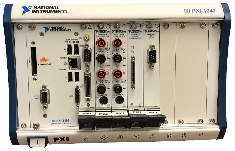
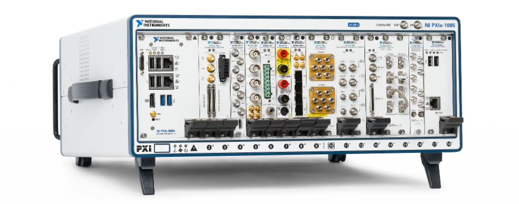
| NI PXI chassis and controller |
| NI PXI acquisition cards for analog measurements |
| NI PXI acquisition cards for digital input and output |
| NI PXI DMM for precision voltage and resistance measurements |
| Audio amplifier for speaker tests |
| INTERFACES / PROTOCOLS |
|---|
| Ethernet |
*- images are conceptual, not actual
Automated Manufacturing Test Systems for Medical Diagnostic Equipment
Automated Manufacturing Test Stands for Medical Diagnostic Equipment
Using NI PXI and LabVIEW as a common architecture for multiple test systems testing several subassemblies
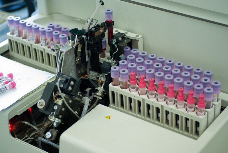
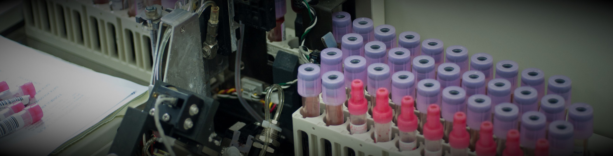
Client: a manufacturer of automated blood analysis machines
Challenge
Our client was embarking on a complete redesign of their flagship automated in-vitro Class 1 blood diagnostic machine. In order to meet schedule goals, the design and build of several automated test systems needed to occur in parallel with the overall machine. In a major design paradigm shift, many components of the machine were being manufactured as modular subassemblies, every one of which was an electro-mechanical device. Thus, multiple testers were required to test each of the specific subassemblies in the machine. And, since this was a medical device, the testers needed to comply to 21 CFR Part 820 and Part 11.
Solution
With a looming deadline, the testers needed a common architecture, so that all testers could leverage the development from the others. Since each subassembly could be tested independently of the overall machine prior to final assembly, the design of the testers was based on a common measurement and reporting architecture, written in LabVIEW, that interfaced to the customers Part 11 compliant database for testing procedures and measurement results. Furthermore, procedures and validation checks for calibration of the testers were part of the overall test architecture.
Benefits
- Modularization of the test system architecture aided development and maintenance
- Reduced overall development costs due to standardization of test sequence steps and reporting
- Both test sequences and test results were stored in a managed database that satisfied 21 CFR Part 11 requirements
- Modular and common software developed for the test systems reduced the V&V effort during IQ & OQ.
System Overview
Since multiple subassemblies were being tested, with one part-specific test system per part, the automated test systems used as much common hardware as possible to simplify the development effort through common hardware drivers and test steps. Test steps and the test executive that executed the test sequence(s) were developed using LabVIEW. Measurements were made with PXI equipment housed in a test stand along with support hardware.
The types of test steps required to verify the proper operation of each subassembly were categorized into basic operations, such as voltage reading, pulse counting, temperature reading, and communications with on-board microcontrollers. The specifics of each measurement could be configured for each of these measurement types so that each test step accommodated the needs of the specifics of each subassembly. For example, one subassembly might have needed to run the pulse counting for 2 seconds to accumulate enough pulses for accurate RPM calculation while another subassembly might have only needed 0.5 seconds to accomplish that calculation.
The configuration of a test step algorithm was accomplished via an XML description. The accumulation of these XML descriptions of each test step defined the test sequence run on that specific subassembly.
Test results were associated with these test sequences by completing the entries initially left blank in the test sequence, so that all results were explicitly bound to the test sequence.
The operator user interface distinguished between released and unreleased test sequences. With unreleased test sequences, engineers could try the most recent subassembly designs without needing to wait for final validation. The released sequences were only available to test operators. This login-driven branching was managed using the Windows login, so that the client employees could use their company badge-driven login process. Once logged in, the user would be able to execute the test sequence in automated mode, where all steps happen automatically, or manual mode, where one step could be operated at a time.
Furthermore, the Windows environment was locked down using built-in user account group policies to designate the level at which a user could access Windows or be locked into accessing only the test application.
V&V Effort
During the V&V effort, each test sequence was verified for expected operation, against both known good and bad parts. Once verified, the sequence was validated against the requirements and, when assured to be as expected, a checksum was applied to the resulting XML test sequence file and all was saved in a Part 11 compliant database. Upon retrieval, when ready to run a test, the sequence was checked against this checksum to assure that a sequence had not been tampered.
Test results, saved as XML in the same file format as the test sequence, were also surrounded by a checksum to verify that no tampering had occurred.
The IQ/OQ efforts were handled in a traditional manner with the client developing the IQ/OQ documentation, with our assistance, and then executing these procedures, again with our assistance.
| SOFTWARE FUNCTIONS |
|---|
| Low-level measurement drivers |
| Measurement-based test steps |
| Test sequence execution |
| Test sequence management |
| User access management |
| Test report creation and management |
| Verification of test sequence content and ability of user to execute |
| Verification of the content of the test results |
| HARDWARE USED |
|---|
| PXI chassis and controller |
| PXI acquisition cards for analog measurements |
| PXI acquisition cards for digital input and output |
| CAN card |
| INTERFACES / PROTOCOLS |
|---|
| Ethernet |
| CAN |
*- images are conceptual, not actual
Manufacturing Test – for mission-critical components

Manufacturing Test – for mission-critical components
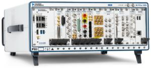
Using PXI & LabVIEW RT
Client: A major manufacturer of implantable cardiac and neural stimulators
Challenge
Our client needed several extremely reliable test systems to test the batteries that power their implantable medical devices. These new test systems were needed for two main reasons. First, the needed to upgrade existing obsolete test equipment, based on antiquated hardware and software. Second, new battery designs could not be tested on the old equipment.
A critical aspect of the new test system was the need to detect any excessive charge being extracted from the battery, thus rendering it unsuitable for surgical implantation. Thus, the test system needed to monitor the total energy withdrawn from a battery during testing to assure that it never exceeded a certain limit while also offering precise control of the type of pulses being drained from a battery.
All test results had to be stored in a database in order to maintain device history for each battery manufactured for archiving, quality control, and process improvements.
Solution
The updated manufacturing test system is PXI-based along with a custom micro-controller-based circuit board for some low-level control. Each PXI controller communicated to the microcontroller (uC) on the custom PCB via CAN. The uC controlled the current drain from the battery while monitoring actual current and voltage from the battery at over 1000 samples per second using a precision 6.5 digit PXI DMM. Additionally, each PXI chassis was used to test many hundreds of batteries. Signal connections were handled by several switch multiplexers. Overall control of all the PXI testers was managed by a host PC connected to the PXI controller.
Benefits
- Reduced test system cost vs complete COTS solution with combo LabVIEW RT on PXI and firmware on microcontroller-based custom circuit board
- Enabled tight control of DUT operation on controller with microsecond level responsiveness while being supervised by higher-level PXI RT
- Quick-reaction test abort capability
- Test results stored to database for archiving, quality control, and process improvements
System Overview
In a simplified view, the testing proceeded by pulsing the battery with a series of different durations and varying amperages. The exact sequence of this pulsing is unique for each DUT model. Measurements were made using a PXI filled with various NI boards such as DMMs, for accuracy, and data acquisition cards, for general purpose use.
Additionally, the pulsing amperage levels needed to be tightly controlled in order to know that the tests have been performed properly. Thus, a real-time amperage control scheme had to be implemented to maintain the level requested for the pulse. We chose to accomplish this control via an analog control circuit developed using a custom Viewpoint-developed circuit board. This board was controlled via a Microchip PIC microprocessor. The LabVIEW RT application communicated with the microcontroller to setup the pulsing sequence and coordinate the start and stop of the pulsing and the NI acquisition hardware.
This custom circuitry also reduced the overall cost of the test system by about 40%.
The engineering time to design this custom circuitry was more than offset by the reduction in material costs because more than 10 test systems were deployed, allowing the non-recurring engineering effort to be shared between many systems.
When no critical issues were detected, the waveforms acquired by the PXI system were stored and then analyzed to determine the viability of the DUT. The pass/fail disposition, the waveforms, the total energy consumed, and other test results were then passed along to a host supervisory PC that managed all these results in a database for archiving, quality control, and process improvements, each set of results being tied to the unique unit serial number.
The test systems provided reliable operation for testing the large annual production volumes of the mission-critical DUTs.
Since we designed the system to interface to our customer’s host supervisory PC via ethernet-based commands, the verification and validation (V&V) process could be supported by our customer in their Installation and Operational Qualification (IQ/OQ) efforts. Specifically, they wrote the IQ/OQ procedures around software that emulated interfacing with the host supervisory PC. This approach allowed them to automate parts of the V&V thus saving them almost 1 week of effort.
| SOFTWARE FUNCTIONS |
|---|
| LabVIEW RT – for managing the microcontroller functions and overall data collection and safety monitoring |
| Microcontroller application – to provide precision pulsing of the batteries |
| Communicate to the host PC – to both receive pulsing instructions and configurations and to return pulse waveforms for each battery tested. |
| MAIN HARDWARE COMPONENTS |
|---|
| PXI chassis & controller |
| PXI DMM |
| PXI analog input modules |
| SCXI multiplexing switches |
| INTERFACES / PROTOCOLS: |
|---|
| Ethernet TCP-IP |
| CAN |
If you need a custom test system for your medical device, reach out here.
You’re cautious and risk-averse because you need to worry about things like 21 CFR Part 820 and Part 11. You need to dot your ‘I’s and cross your ‘T’s.
We understand.
Our expertise in the medical device industry focuses on test system development. Your test system needs go beyond what other non-regulated industries are accustomed to. Specifically, you need to manage the development and delivery processes to assure that the test system covers all the test requirements and does exactly what it was designed to do. Build the right thing and build the thing right, as the saying goes.
These processes need to satisfy 21 CFR Part 820 and, nowadays, almost certainly Part 11 for any electronic records, including the software which the test system runs and any records it produces. We understand that the development of any test system we design and build for you would need to follow your IQ/OQ/PQ processes and we would work closely with your Quality Team.
We find sometimes that our clients need assistance in developing the test requirements documentation because that process often requires an understanding of the capabilities of test hardware. We can collaborate with you on that effort.
Bottom line: we understand the regulated environment you live in. Part 820 and Part 11 provide guidelines for good manufacturing processes, and we’ve been seeing these development and delivery concepts being adopted in other non-medical industries. Our clients are increasingly seeing the benefits of doing the right thing and doing the thing right, just like you (and we) have been doing for a long time.