Aerospace Test Systems | Defense Test Systems
Custom Test Equipment for Aerospace and Defense Manufacturing
You’re risk averse and your customers expect a high level of rigor because your products are mission-critical.
With over 300 aero-def test solutions delivered, our aero-def expertise is focused on test system development for mission-critical components and sub-systems.
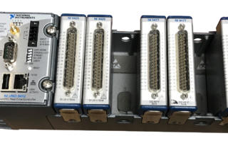
We’ve designed and developed test systems for many types of LRUs and subcomponents used in aerospace and defense applications. For example: flight surface actuators, ECUs via emulation of connected hardware, EO/IR imaging focused on FPA/ROIC electronics, hydraulic valves, gas valves, and others that require rigorous, traceable testing.
![]()
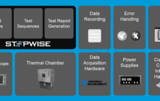
How we can help: our capabilities & expertise
Types of Aerospace Test Systems Viewpoint Develops
Want more proof points? Check out the AeroDef case studies below.
These case studies describe some of the test systems we have delivered. The test stands (or test rigs) combine hardware and software used to automate the rigorous procedures needed to verify and validate mission critical products.
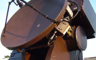
Transonic Wind Tunnel Test System Upgrade
Transonic Wind Tunnel Test System Upgrade Improved Reliability, Reduced Stress, and New Tools People Want to Use. Client - Calspan (tunnel image courtesy of Calspan) Challenge Calspan operates a transonic wind tunnel capable of continuous Mach-speed testing a wide range of aircraft designs. The overall test system was comprised of three subsystems that were all state of art at the time of design, over 20 years ago, but components were either obsolete or soon becoming so. [...]
Selecting replacement hardware for an obsolete test system
Selecting replacement hardware for an obsolete test system A disaster hits – repair to meet schedule, and then upgrade after Client – A major aerospace company Challenge Our client’s design validation test system was about 10 years old. They realized that the NI hardware in the test system was soon to be obsolete and they would have to upgrade it someday. That day came sooner than expected when an issue in the test cell [...]
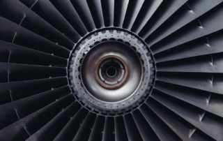
Manufacturing Test System – Aircraft turbine blade quality inspection
Manufacturing Test System – Aircraft turbine blade quality inspection Improving quality by detecting blocked holes in aircraft turbine blades with an automated test system Client - Large aerospace company Challenge Fuel-fed aircraft turbines run extremely hot. At very high temperatures, a turbine’s blades suffer a shorter life span than if run at cooler temperatures. Consequently, turbine manufacturers put cooling holes in the blades to lower the blade temperature during operation. These holes carry [...]
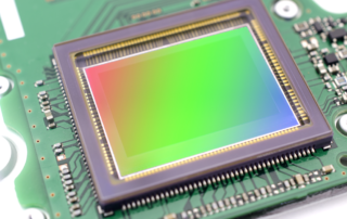
Automated production test of EO/IR imaging subsystem
Automated production test of EO/IR imaging subsystem Assessing quality of mission-critical electronics for imaging Increased throughput by automated signal skew adjustment and pixel verification Client - Worldwide supplier of products for aerospace and defense Challenge Our client wanted a test system that would significantly increase production rates for a very specialized focal plane array (FPA) and associated readout integrated circuit (ROIC) electronics. In broad strokes, the system needed to support the following: Increase production [...]
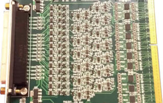
Replacing Wire-wrap Boards with Software, FPGAs, and Custom Signal Conditioning
Replacing Wire-wrap Boards with Software, FPGAs, and Custom Signal Conditioning Electronic components of fielded systems were aging out Reverse engineering effort converted wire wrap boards to FPGA-based I/O Client - Amentum - A supplier for Military Range System Support Challenge Amentum (www.amentum.com) supports a decades-old system deployed in the early 1980s. While the mechanical subsystems were still functioning, the wire-wrapped discrete logic and analog circuitry was having intermittent problems. Systems designed and built decades ago [...]
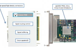
Custom FlexRIO Adaptor Module supports HIL Test Upgrade
Custom FlexRIO Adaptor Module supports HIL Test UpgradeA custom-COTS approach reduces cost and delivery time. Client - Major National Research Lab Challenge Our client has a client (the end-user) for which they developed an HIL test system several years prior. Parts were obsolete and the system needed an upgrade. The prior system had many custom-designed electronic components which could not be replaced without a complete redesign. Consequently, our client wanted to use COTS. However, one device needed [...]
High-Speed Digital Subsystem Emulator
High-Speed Digital Subsystem Emulator Client: A large company involved in C4ISR At maximum throughput, the AEDIS systems needed to consume and produce more than about 800 MB/s/slot. Background A large company involved in C4ISR was developing a system for a new high-speed digital sensor device. Viewpoint was contracted to build a test system used in design validation and ultimately endurance testing of the sensor. Since the sensor was a component of a larger system which was [...]
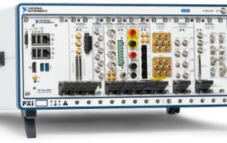
Endurance Testing using NI PXI
Endurance Testing using NI PXI An automation test stand permits faster validation, unattended test, an increase in throughput, and can free up resources for other tasks during the weeks long endurance test. Client - A manufacturer of aircraft components in the mil-aero industry Challenge New product development drove the need for a new aerospace endurance test stand for product validation. The old systems were not designed to test the newly designed part (aircraft actuators), [...]
Endurance Tester for Mission-Critical Mechanical Component using NI cRIO
Endurance Tester for Mission-Critical Mechanical Aerospace Component using NI cRIO Ability to run tests unattended and overnight reduces operator labor and compresses test schedules Client - Major Aerospace Component Supplier / Manufacturer ChallengeThe client had an older VB & PLC-based aerospace test bench in place already, but it was obsolete. A new endurance test bench needed to be developed to validate prototyped components (in this case, aircraft & aerospace bearings). Many of the prototypes are [...]
Product Validation using LabVIEW RT & LabVIEW FPGA – Electromechanical Actuator Test Stand
Product Validation using LabVIEW RT & LabVIEW FPGA - An electromechanical test stand for an aerospace actuator Automated testing reduces operator man hours and increases production throughput. Client - A manufacturer of actuators in the mil-aero industry. Challenge New Product Introduction (in this case a new controller and new actuators) drove the need for a new aerospace electromechanical test stand. Solution New NI PXI-based electromechanical test [...]
Product Validation & Production Test System – For complex Mission-critical sub-system
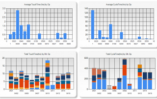
Product Validation & Production Test System - For complex Mission-critical sub-system Client Ensign-Bickford Aerospace & Defense Upgrade reduces per unit test time by ~40% and improves reliability of software Challenge The customer needed to upgrade their existing test system. Their old test system was very manual: It did not provide ability for unattended operation The thermal control had to be set manually They wanted to do less manual review of the data [...]
Hidden Factory Assessments Lead to Waste and Cost Reductions
Sharing Business and Test Data Enables Efficiency Improvements Reduce Production Costs by Coordinating Business and Test Data Client: A major manufacturer of aerospace components Problem ScopeMany companies operate in a high-mix, low-volume manufacturing environment. In these situations, production of such parts is often complex, with long assembly and test procedures describing the process to make and verify the part. Discussions of automating any part of these processes are often dismissed because an automated test system is [...]
Decreasing Test Time for Aircraft Landing Gear
Decreasing Test Time for Aircraft Landing Gear Endurance Testing for Aircraft Nose Landing Gear Steering Client: A major manufacturer of aircraft landing systems Challenge A major manufacturer of aircraft landing equipment needed to develop a means of endurance and fatigue testing new designs for aircraft steering. The actuators involved in steering the nose landing gear (NLG) required precise and reliable control through thousands of steering cycles. Control loops needed to be closed at faster than 1 ms. [...]
If you need a custom test system for your mission-critical aero-def component, reach out here.
Want to learn how to make your assembly and test process a competitive advantage? Check out this webinar »
Poll – Test engineering leaders: What would help you most? Vote and see how your peers voted!
We’ve helped teams at some of the world’s most innovative companies