cRIO LabVIEW Programmers
With over 500 cRIO-based solutions under our belt, we’ve utilized the cRIO for a number of test and industrial embedded applications. The FPGA and variety of I/O modules make it a formidable choice for many applications.

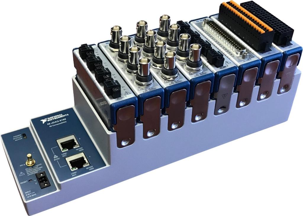
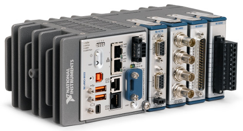
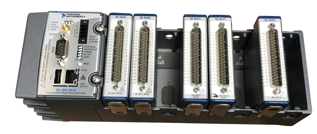
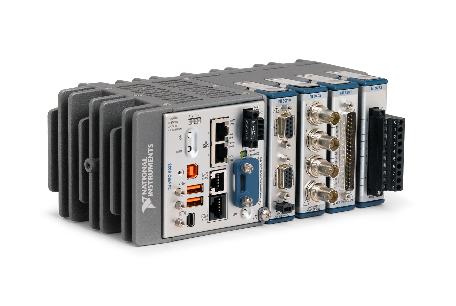
NI’s Compact RIO platform is great for projects that need essentially a small PXI. Combining a cRIO controller with the multitude of C Series modules creates a functional real-time controller for many applications in a small footprint. The cRIO is often used as a standalone system, and even as an embedded system as part of an OEM machine. The FPGA built into cRIO offers very fast control loops for situations needing rapid response outputs. cRIO can make a symbiotic addition to a PC-based application that requires some aspect to be real-time.
Viewpoint has used the cRIO in applications that need a moderately powerful controller to perform real-time monitoring and sometimes control as well. Coupling the variety of C Series modules with LabVIEW RT and LabVIEW FPGA allows us to support many types of real-time applications:
- Product validation
- Endurance testing
- Machine monitoring
- Production testing.
Adding the cRIO’s FPGA capabilities opens up those applications to very fast control loops (100+ kHz) and essentially hardware-driven control and monitoring for critical applications with expensive assets.
Trying to select test hardware but overwhelmed by NI’s massive catalog of hardware options? Whether you’ve got a BOM started and looking for confirmation that you’re on the right path, or you’re not even sure where to begin, check out our NI Hardware Selection Services for help.
Want more proof points? Check out these cRIO case studies:
Subsea Oil Rig Device Communications with NI cRIO
Subsea Oil Rig Device Communications with NI cRIO
Off-the-shelf controller connects riser and blowout preventer components to topside operations
Client – Kongsberg Maritime – a global leader of systems for subsea oil and gas extraction
Challenge
Kongsberg decided to offer, as part of their overall Riser Management System (RMS), a system that contained a real-time communications hub for monitoring parts of a subsea drilling rig, including the Blowout Preventor (BOP), components of the Lower Marine Riser Package (LMRP), and 3rd-party devices.
The purpose of this hub was to aggregate data from subsea devices and send to topside control and monitoring systems. It would sit alongside other devices needed for subsea operations, such as power supplies, an Ethernet router, and a DSL comm driver.
Foremost, the hub needed to be robust and reliable: subsea maintenance is expensive. Expandability of the hub was also important to accommodate a variety of the types of inputs and communications protocols as features sets were adjusted according to customer and market needs.
This hub was intended to expand connectivity to the RMS beyond traditional riser monitoring, enabling full interoperability with intelligent subsea systems and instrumentation.
Solution
Since Kongsberg defined the overall system concept, architecture, and requirements as part of the broader Riser Management System (RMS) strategy, Kongsberg had intimate understanding of the needs of this data hub. Kongsberg reviewed options for the controller and the planned set of features and chose to use an NI Compact RIO (cRIO) controller.
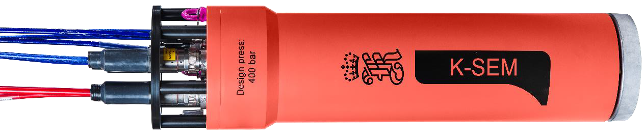
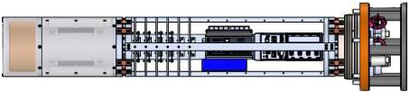
The cRIO is combined with other components and that bundle is called K-SEM for Subsea Electronic Module. The other components in K-SEM include custom power supplies, DSL communications, additional Serial interfaces, analog inputs, an Ethernet Router, and so on. This case study focuses on the communications and data collection usage provided by the cRIO.
The K-SEM system supports more communications protocols such as Modbus, CAN, OPC UA, and custom protocols which can be developed using the cRIO’s FPGA. Furthermore, K-SEM can support analog inputs from strain gauges, LVDTs, pressure and temperature transmitters, and any other general-purpose analog input. Other devices such as cameras are also supported. All data was collected by the cRIO and output topside via OPC-UA.
The exact configuration changes according to the modules installed in the cRIO chassis, the software developed for those modules, and the desired communication protocols to support.
Working Together
Early on, Kongsberg had identified the Compact RIO (cRIO) controller as a platform for the monitoring system. Kongsberg sought a software partner that had deep experience with LabVIEW RT and cRIO development. Viewpoint Systems was selected. Our role was to support the development efforts based on Kongsberg’s design to make K-SEM a reality. Kongsberg retains full ownership of the design, architecture, and software sources and we worked closely with the Kongsberg team to make sure they had a clear understanding of what we jointly developed.
Part of the reason Viewpoint was selected was based on our initial discussions with Kongsberg when we reviewed the planned feature set and joint development approach. Kongsberg had done a solid review of cRIO capabilities; Viewpoint’s experience with the cRIO added a layer of assurance that this platform would do the job.
We took a very deliberate development approach. Even though each iteration followed a defined path from requirements to verification to deployment, the iterations were incremental enough that the initial version of K-SEM grew in capability controllably and confidently.
Viewpoint worked closely with our engineering colleagues at Kongsberg to develop the approaches to achieve the features. Since we did not have access to the complete K-SEM system components, Viewpoint developed and delivered in the USA while the Kongsberg engineering team tested and gave feedback while in Norway.
This collaboration effort was performed in three parts:
- development,
- debugging, and
- acceptance testing.
Development
For development, Kongsberg and Viewpoint exchanged documents and discussed the requirements for the next phase of incremental development. Viewpoint then wrote the LabVIEW RT code to implement the features. The source code, build, and configuration files were hosted in Viewpoint’s Microsoft Azure Dev Ops account and shared with Kongsberg.
Debugging
For debugging, we connected remotely to a laptop in Norway via TeamViewer to debug the deployment on the cRIO. Kongsberg had a few Modbus devices connected to the cRIO so we could verify being able to read Modbus data. The OPC UA output from the cRIO was checked by using UaExpert as the OPC UA client and validating that the received OPC UA data was correct.
Acceptance Testing
For acceptance testing, an image was created, deployed on the cRIO, and then Kongsberg and Viewpoint engineers would join a Teams calls while using TeamViewer to run through a thorough and formal acceptance test. Once everything passed, the image was deployed to systems into the field. This acceptance testing step was of course very important since the cRIO was being deployed in a hard-to-reach location subsea.
A cell modem was used for the Ethernet connection to satisfy IT security needs.
Benefits
The K-SEM system was motivated by a market demand to reveal more information to the operator about the behavior of the LMRP and control of the BOP while the rig was in operation. Being able to connect to an Intervention Workover Control Systems (IWOCS) skids was also beneficial for a temporary control system used to commission, workover, troubleshoot, or decommission subsea wells.
The K-SEM acted as a data hub to connect all these subsea devices and sensors with the topside facility.
The flexibility of the cRIO platform, with its family of plug-in cSeries modules and controller capabilities, enabled the integration of subsea systems and sensors, especially with the diverse protocols and media employed by various third-party vendors.
Pushing all the data to topside requires reliable and high-speed data transmission, especially for analog sensors running at a high sampling rate. This requirement had been a persistent challenge for the industry until COTS devices such as the cRIO became available.
How we helped
With Kongsberg driving the design, system architecture, and requirements, Viewpoint’s role was to take these elements and apply our skills in LabVIEW RT and cRIO hardware to create a functional and reliable software application.
The tight collaboration Viewpoint had with Kongsberg resulted in direct and efficient discussions of points needing clarification during our development. Likewise, with our knowledge of the cRIO and LabVIEW RT, we gave feedback to Kongsberg about good ways to implement the requirements and prepare for testing the application.
These discussions were helpful for giving Kongsberg an understanding of the details. Kongsberg was responsible for testing the developed application; Viewpoint supported that effort.
Viewpoint’s high-level roles in the development of the K-SEM were as follows.
- LabVIEW RT expertise and consulting
- Extensive cRIO application development experience
- Collaboration with Kongsberg on design and development of cRIO software
- Remote engineering for system development and testing
The tight collaboration between both Viewpoint and Kongsberg teams created a great environment for this development effort. The fact that we were separated by an ocean was immaterial.
System Overview
K-SEM connects the cRIO to a variety of devices, collects the data, and sends it topside via OPC UA. The topside facility uses this information to control operations subsea on the LMRP, BOP, and other devices as needed.
Devices typically interfaced are:
- Motion Reference Units (Kongsberg MRUs)
- Power supplies
- LVDT sensors
- Distributed Kongsberg devices with Modbus comms
- Third-party devices with a variety of comms:
- Serial, Ethernet, Ethernet on DSL, and Modbus
- Cameras with subsea lights and lasers
Most of these units used Modbus to transfer messages and data. The K-SEM supports CAN, NMEA messages, and custom FPGA-based protocols as well.
Some sensors were used to acquire waveform for time-domain and FFT analysis. These waveforms create a significant amount of data to send topside via OPC UA but the bandwidth of standard Ethernet is capable of sending waveforms and all the other slower speed data points.
The capabilities of the K-SEM are an integral part of Kongsberg’s overall strategy of enhancing visibility of the Riser Management System (RMS) by including subsea digitalization and integration with third-party systems.
Overview of system components
| SOFTWARE FUNCTIONS |
|---|
| LabVIEW RT |
| OPC UA |
| DAQmx |
| HARDWARE USED |
|---|
| Compact RIO controller (e.g., cRIO 9022 or equivalent) |
Manufacturing Test System – Aircraft turbine blade quality inspection
Manufacturing Test System – Aircraft turbine blade quality inspection
Improving quality by detecting blocked holes in aircraft turbine blades with an automated test system

Client – Large aerospace company
Challenge
Fuel-fed aircraft turbines run extremely hot. At very high temperatures, a turbine’s blades suffer a shorter life span than if run at cooler temperatures. Consequently, turbine manufacturers put cooling holes in the blades to lower the blade temperature during operation. These holes carry cool air or gas from the blade mount along channels that eventually arrive at holes in the blade surface. This practice keeps the blade much cooler than without the flow.
Some blades have a huge number of holes. Inspecting that each hole is open and has sufficient flow is time-consuming and, if inspected by a person, prone to error due to boredom and distraction. Plus, carpal tunnel syndrome issues are present due to repetitive motions. Multiply these issues by the large number of blades in each turbine and inspection becomes a significant effort.
Our client wanted to implement an automated inspection station to increase throughput and decrease mistakes. Sending defective blades down to the subsequent manufacturing steps is pure manufacturing waste when they are rejected at some later step. Reducing operator injury was also important.
Image courtesy of CC by 4.0 https://creativecommons.org/licenses/by/4.0/ from Zhang, R.; Liu, P.; Zhang, X.; Xi, W.; Liu, J.; “Recent Developments in the Aerodynamic Heat Transfer and Cooling Technology of Gas Turbines Endwalls”. Aerospace 2023, 10, 702. https://doi.org/10.3390/aerospace10080702
Solution
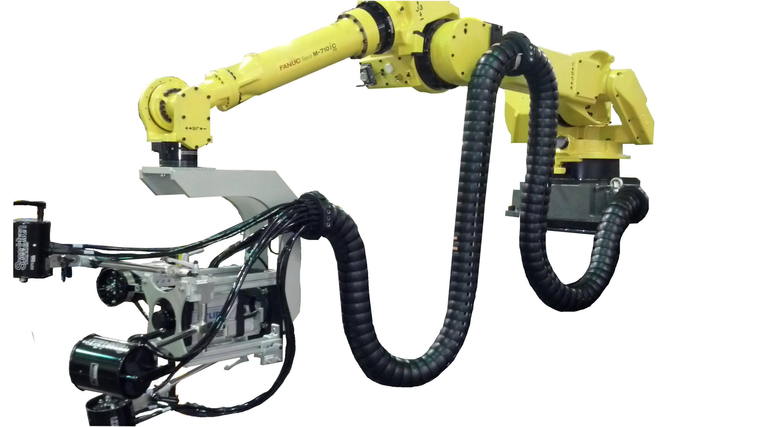
Collaborating with our client, we created a manufacturing inspection system that uses an IR camera and a robot to scan different regions on the blade under inspection. The camera is placed at specific locations and at various viewing orientations to fully inspect all the holes in the blade.
A PC running a LabVIEW test application manages the entire process. Safeties and control of access to the part under inspection are included to protect personnel and product. The system uses hardware sensors and switches and some via FPGA I/O to accomplish this safety monitoring.
Working with our client and our machine builder subcontractor, we helped select the NI hardware best suited for this test system. Our primary focus was on the interface between the IR camera and the system safeties.
Benefits
- The reliability, reproducibility, and speed of the automated inspection augments the operator capabilities
- Improved part quality of parts released to downstream production steps.
- The measurements collected during inspection of each part are available for quantitative analysis of the performance of the manufacturing processes. This post-inspection information helps improve quality all around.
Working Together
This project was the culmination of over 10 years of development effort between our client and Viewpoint engineers.
We started with a basic R&D proof of concept system.
After some tweaks to the process and associated system redesign, we were ready to use a prototype system in a trial run situation where manufactured parts were run manually. This stage gave confidence to those in manufacturing that the system would improve part inspection while speeding up the original manual inspection process. Some changes were made at this stage to decrease costs and improve the test engineer and operator interfaces. It was then placed into the production environment.
Along this entire multi-year development path, the level of automation was increased and the system design was adjusted as we learned from each other about what worked and what didn’t. For example, early in the R&D phase, attention was paid to the analysis algorithms and data required to make those reliable and accurate. And, for the production phase, we changed hardware components to make the test stand hardware less expensive and more robust while reworking the user interface of the software application to be simpler to configure and run.
Both Viewpoint and our client formed a tight team during this journey, with one constant being the Viewpoint engineers involved as the various people on the client’s side changed as this inspection system moved through departments and physical location within our client’s facilities, eventually culminating as a complete test rig with a robot, test stand for data acquisition control, and safety components to protect the operator.
System Overview
The system is composed of the following items:
- Test stand and control hardware cabinet
- LabVIEW test application running on a PC
- Robot and motion controller
- Vision system for IR camera
- NI Compact RIO FPGA digital I/O for controls and safeties
- NI Compact RIO analog I/O for equipment status
- Hardwired safeties and switches for operator and equipment protection
The LabVIEW application manages the entire inspection cycle:
- Assuring a part is present in the nest before starting the inspection process,
- Downloading the part-specific motion profile to the robot,
- Acquiring the images from the IR camera,
- Analyzing the images,
- Compiling the results, and
- Preparing a test report for the part.
Simultaneous with this cycle, the application checks digital and analog I/O for machine status and errors.
If a part model has not been inspected before, the LabVIEW application is used to create the motion profile for that part model.
When the test on a specific part is started, that motion profile is downloaded to the motion controller based on the part type as selected in the application.
After testing a part, the operator is presented with the test results where the option to accept, retest, or reject is offered. The operator is integral to this automated test. In any case, the test data is archived.
When the test is completed, the operator unloads the part for final disposition and loads the next part to inspect.
The LabVIEW application also has a diagnostic mode and configuration editor which is used by the operator or manufacturing engineer to evaluate and tune the inspection process.
The robot movement is managed by a motion controller based on the motion profile created via the LabVIEW application. The PC-based image acquisition is done when the motion controller alerts the LabVIEW application that the part is oriented and positioned within the field of view of the camera. Images are acquired for each of the positions defined in the motion profile.
Safety for both the operator and the part is handled in two ways. First, the Compact RIO FPGA checks system status via digital and analog inputs. Second, hardwired safety sensors and switches assure that the operator is out of the way when the robot starts moving and that the part is in the nest ready for inspection. An example of these “hard” sensors is a light curtain which will cause the system to stop if the curtain is affected during a test.
| SOFTWARE FUNCTIONS |
|---|
| NI FPGA for control and safeties |
| PC LabVIEW test application |
| System configuration |
| Data management |
| Safeties and machine status |
| HARDWARE USED |
|---|
| Articulated robot |
| Vision camera |
| FPGA digital I/O |
| FPGA analog I/O |
| Hardwired safety circuit for personnel and product protection |
| Touchscreen monitor |
Custom electronics and COTS hardware combine into a unique torque measurement system
Custom electronics and COTS hardware combine into a unique torque measurement system
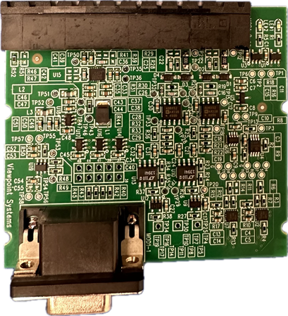
Custom electronics C Series module designed for pulse detection.
A combined custom and COTS Compact RIO solution provides simpler maintenance and longer lifecycle.
Client
Large international supplier of motors, coupling components, and related equipment
Challenge
Our client had an existing torque measurement system that was designed and developed many years ago. Components for it were obsolete and remaining inventory was limited. Tech support for their world-wide clients was about to become a critical challenge. A replacement torque measurement system needed to be designed and built.
We were contacted to leverage our expertise in four areas:
- Custom electronics design and build,
- NI’s embedded Compact RIO (cRIO) systems,
- Expertise in reverse engineering, and
- Operator application development.
An important part of the challenge was that we needed to reverse engineer the existing system because of incomplete documentation about the operation of the system under the wide range of use cases.
Also, the client wanted us to update the operator application used for:
- real-time display of measurements,
- configuration of the measurement system,
- and initial system installation checkout,
among other features.
Finally, and importantly, the hardware needed to be Class 1/Div 2 compliant for operation in a hazardous environment, along with CE and UL conformance.
Solution
We decided to use the NI cRIO platform since it was ready for use in an industrial setting, having specifications such as extended temperature range, large shock and vibration capability, a small physical footprint, and the required Class 1/Div 2 certifications. This approach reduced the review for Class 1/Div 2 compliance, and the certifications from CE, FCC, and UL, to be mainly focused on our custom electronics, although, of course, the entire system needs to comply too.
The NI cRIO selected for this project consisted of:
- a controller,
- a chassis,
- and various COTS C Series modules for signal measurement and communications I/O.
Significantly for this project, the cRIO platform offered a hardware development kit, which enabled us to design and build a custom C Series module containing the custom electronics to convert signals output from the customer-supplied sensors into torque measurements.
Benefits
Besides the obvious benefit of relieving our client’s tech support urgency, caused by the shrinking parts inventory, this new system is:
- more maintainable due to much of the hardware being off-the-shelf,
- customizable since much of the functionality is provided by software, and
- supportable since the components are reconfigurable and modifiable.
Because most of the system “smarts” are delivered by software in this redesigned system (not by a specific hardware design), feature updates and tech support are simpler and more manageable than with the previous system. In fact, when it was found that some of the initial requirements were not well described by the client, we leveraged this flexibility during system debug to maintain the delivery schedule.
Since most of the system is made from off-the-shelf components, the client benefits from NI handling much of the hardware lifecycle management. Now the client only needs to focus on the custom C Series module we provided, a much smaller task and one which we can help them monitor as needed. An important consideration in our design was component life cycle so the client need not worry about obsolescence for many years.
System Overview
The signals from the two position sensors are manipulated by our custom electronics to convert them to digital pulses. The essence of this manipulation is signal-amplitude-dependent thresholding combined with de-bouncing hysteresis. The custom electronics uses an on-board FPGA to communicate with the cRIO chassis and, with custom VHDL interface code, to provide data to LabVIEW FPGA I/O nodes. That data is then passed to the cRIO FPGA to detect the edges of the two digital signals and timestamp them with high resolution.
The time delay between the two edges is converted to a torque measurement through a calibration procedure. The calibration information is supplied by the client and can be modified to account for different mechanical configurations of the couplings and shafts used by their clients. The environmental temperature, measured by a COTS C Series module, is incorporated into that calibration correction.
The measurements available from the system are:
- torque,
- speed,
- temperature,
- and horsepower.
These values are held in the system’s Modbus registers. Various other parameters are sent back and forth between a PC and the cRIO controller for configuration, system status, and troubleshooting as needed.
We developed a LabVIEW Windows application for a PC through which the users interact with the torque measurement system. This PC application handles the communication between and configuration of the cRIO as a Modbus Slave device using TCP and/or 485 signals. A PLC also communicates with the system for controlling their motor, monitoring their equipment, and performing safe shutdown if needed.
LabVIEW was used for the applications on the Windows PC and the embedded cRIO. Part of the cRIO embedded app used LabVIEW RT and part used LabVIEW FPGA. The latter was needed to tap into the cRIO’s FPGA for its 25 ns resolution for the time delay measurements. That resolution, some signal processing, and the sensor calibration resulted in excellent performance.
| SOFTWARE DEVELOPED |
|---|
| LabVIEW Windows application for configuration, troubleshooting, and real-time display. |
| LabVIEW RT and LabVIEW FPGA application to interface to the sensor waveforms and produce torque measurements. |
| Modbus communications for connectivity to the Windows PC and to a PLC used for monitoring, control, and safe shutdown. |
| HARDWARE USED |
|---|
| Custom signal conditioning electronics to convert sensor waveforms to digital pulse trains. |
| Custom c-series module enclosing the signal conditioning electronics. |
| cRIO chassis containing custom C Series and temperature measurement module. |

Custom Automated Test System – Quantifying Energy and Durability Performance for Refrigeration

Custom Automated Test System – Quantifying Energy and Durability Performance for Refrigeration
Automation reduces manual labor while improving traceability
Assessing performance for improved energy ratings and longevity
Client – Zero Zone – Commercial refrigeration systems manufacturer
Challenge
Zero Zone wanted to improve the capabilities and durability of their new reach-in refrigeration products.
You might think that refrigeration is a mundane product line, but that is just not true! So many innovations are occurring as manufacturers are redesigning their products to improve their environmental footprint through better energy efficiency, coolants, and durability.
Assessment requires an understanding of the performance of the refrigeration units under many conditions. Zero Zone was taking measurements with a datalogger with too few channels, and no synchronization, to other devices that feed into the system. Plus, they had multiple models of their reach-in refrigerators that needed to be assessed. Furthermore, simplifying the data collection and analysis would make it easier to validate against ASHRAE standards.
Zero Zone came to Viewpoint with the following high-level desires:
- Expand the measurements by adding more channels and channel types (e.g., 4-20 mA, ±10 VDC and digital I/O).
- Provide graphs and KPIs to enable faster analysis of the data during the test.
- Minimize the chance of data loss during long test runs.
- Synchronize data collection and actuation.
- Automate storage of measurements per a user-defined period to eliminate manual start/stop of data collection.
- Simplify the manual configuration setup.
- Enable a way to find relevant data perhaps months or years after the test run.
Solution
Viewpoint developed a monitoring and control durability test system that could exercise Zero Zone’s refrigerators through hundreds of operation cycles over multiple conditions to simulate actual usage in, for example, a grocery store.
During initial conversations, we collaborated closely with Zero Zone to brainstorm on some potential approaches. We made some suggestions that could satisfy their desires while also managing their time and cost budgets. Part of that process involved helping Zero Zone in the selection of the cSeries modules, to assure the most effective modules balancing cost per channel, connectivity, and anticipating some possible future needs.
As an example, by automatically populating the cells in an Excel template based on their original systems’ Excel spreadsheet, we provided streamlined report generation without having to rewrite all the calculation code embedded in their Excel file in another app. The compromises we jointly endorsed were:
- Run an app on a PC to configure and monitor the test.
- Use both NI Compact RIO and Compact DAQ to enable robust and synchronized data collection and control with the ability to expand channels by adding modules in both the cRIO and cDAQ chassis.
- Store data on a local PC rather than a remote server to minimize the probability of data lost during the test run.
- Save configurations into Excel files for recall, and cloning, of prior setups.
- Write measurements automatically into the same Excel file for archive of the test setup and measurements.
- Create, in this same Excel file through cell formulas, the summary report from the summary calculations. This approach allowed flexibility for changes to internal and external test standards.
- Upload the summary data and test reference info into a SQL database for data management and long-term test statistics.
Digital outputs (DOs) were used to control various aspects of the test, such as door open/close and defrost on/off cycles. For flexibility, the user can specify the sequencing of these DO channels, in the Excel file used for the test, with various parameters that define the duty cycle, period, number of cycles, and start delay. The timing of these DO state changes was synchronized to the data acquisition by the real-time loop in the cRIO.
This system was deployed to 6 test bays, each one of which might be testing a unit for as little as a few weeks or as much as a few months.
Benefits
The main goal of this project was to reduce the effort and associated human error in the design and execution of the test run.
Some of the primary benefits for this automated system were:
- Reduced Errors: pre-verified template files used for test configuration and data storage lent consistency to test setup and execution.
- Less Testing Time and Effort: the automatic execution of the test and storage of measurements enabled running tests for multiple days (and nights) without technician interaction. Technicians could work on setting up other units for test rather than babysit the existing test. On average, based on the duration of the test time, testing throughput increased by approximately 25% to 40%.
- Shorter Reporting Time and Effort: reports were available about 85% faster than the time previously spent creating manually. The quicker feedback saved costs through early detection of unit problems and faster teardown at the end.
Some additional major benefits were:
- More details on refrigerator operation: “Wow! We never saw that before.”
- Database consolidation: statistical analysis takes hours not days and includes all tests run in the lab, not just ASHRAE tests. This central database enables long term retrieval of all test data.
- Reuse: techs embraced ability to reuse and modify previous setups.
- Consistency: driving the test definition through an Excel file encouraged uniformity.
- Traceability: documented and timestamped calibration measurements.
- Flexibility: channel counts, acquisition modules configuration, calibration, and calculation formulas were straightforward to change for new test setups.
The test automation provided by this system greatly reduced the labor involved in configuring, running, and analyzing the test run. Furthermore, the customer benefited from the consistency that resulted from the software-enforced process.
System Overview
We developed the application in LabVIEW and LabVIEW RT combined with a cRIO connected to a cDAQ via TSN Ethernet.
The data acquisition modules slotted into the cRIO and cDAQ chassis handled the I/O to the customer sensors and actuators. The sensors mostly measured:
- temperature,
- pressure,
- flow,
- power, and
- voltage.
| SOFTWARE FUNCTIONS |
|---|
| Data logging of between 50 and 150 channels and control via digital signals |
| Interface with Excel files for configuration, data logging, and summary calculations |
| SQL database for summary and test setup data |
| Real-time loop for robust operation |
| HARDWARE USED |
|---|
| NI cRIO 8-slot chassis, TSN enabled |
| NI cDAQ 8-slot chassis, TSN enabled |
| Various NI cSeries signal conditioning modules |
Replacing Wire-wrap Boards with Software, FPGAs, and Custom Signal Conditioning
Replacing Wire-wrap Boards with Software, FPGAs, and Custom Signal Conditioning
Electronic components of fielded systems were aging out
Reverse engineering effort converted wire wrap boards to FPGA-based I/O
Client – Amentum – A supplier for Military Range System Support
Challenge
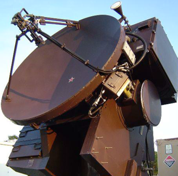
Amentum (www.amentum.com) supports a decades-old system deployed in the early 1980s. While the mechanical subsystems were still functioning, the wire-wrapped discrete logic and analog circuitry was having intermittent problems.
Systems designed and built decades ago can sometimes have wonderful documentation packets. Nevertheless, we’ve been burned too often when the docs don’t incorporate the latest redlines, last-minute changes, or other updates.
The replacement system needed to be a form-fit-function replacement to land in the same mounting locations as the original equipment with the same behavior and connections. Below is an image of the existing wire-wrap boards and their enclosure. We had to fit the new equipment in this same spot.
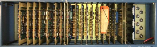
Figure 1 – Original wire-wrap boards
Finally, Amentum wanted to work with Viewpoint in a joint development approach. While our joint capabilities looked complementary, we didn’t know at the start how well we would mesh with our technical expertise and work culture – it turns out we worked extremely well together as a team and neither one alone could have easily delivered the solution.
Solution
Since the team treated the existing documentation package with suspicion, we adopted a “trust but verify” approach. We would use the documents to give overall direction, but we would need details from the signals to verify operation.
Leveraging Amentum’s experience with the fielded systems, the team decided early on to record actual signals to understand the real I/O behavior. We used the system’s “test verification” unit to run the system through some check out procedures normally run prior to system usage. This verification unit enabled us to use a logic analyzer for the I/O to and from the discrete logic digital signals and an oscilloscope and DMM for the analog signals. The available schematics were reviewed to assure that the signals made sense.
With a trustable understanding of system operation, Amentum created a requirements document. We jointly worked on the design of the new system. There were both an “inside” system (in a control shelter) and an “outside” system (in the unit’s pedestal).
Some overall tasks were:
- Viewpoint recommended an architecture for the inside application running on PXIe LabVIEW RT and FPGA layers.
- Amentum created the system control software on a Linux PC.
- Viewpoint developed the more intricate parts of the inside application and mentored Amentum on other parts they developed. This work recreated the existing discrete logic and analog I/O using PXIe NI FPGA boards.
- Viewpoint designed custom interposer boards to connect harnesses to the NI PXIe equipment, including a test point and backplane boards.
- Amentum designed and developed the cRIO-based outside system application and Viewpoint created a set of custom interposer boards to connect harnesses to the cSeries modules.
Critical to this project was our hardware selection services. By combining our engineering skills for the reverse engineering of the legacy electronics with our knowledge of the NI hardware, we narrowed the hardware choices to a few NI FPGA boards.
These PXIe FPGA boards and cRIO FPGA-backed modules handled the required 60 MHz clock-derived signals with correct phases, polarity, analog inputs, and so on. Furthermore, the wire-wrap boards were register-based so the PXIe had to decode “bus signals” sent over a Thunderbolt bus to emulate the programming and readouts from the various wire-wrap boards.
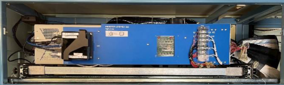
Figure 2 – PXIe replacement to wire-wrap boards
Amentum wanted to be able to support the LabVIEW FPGA VIs used to replace the functionality of the discrete logic. So, Viewpoint acted as mentor and code reviewer with Amentum to ramp them up on using LabVIEW FPGA effectively. Neither one of us alone would have been successful coding the applications in the allotted time. Joint knowledge and experience from both Viewpoint and Amentum were required.
Signal conditioning and harnesses needed to be reworked or replaced as well, of course, since the landing points for the wires were different in the new system. Viewpoint suggested a technique, which we’ve used frequently in past obsolescence upgrade projects, to create PCB boards that accepted existing connectors.
For the cRIO, these interposer “connection” PCBs plugged directly into the cRIO cSeries module. For the PXIe, these interposer PCBs accepted the field wiring connectors and converted them to COTS cables that connected to the PXIe modules. These interposer PCBs could have signal conditioning incorporated as needed. This approach significantly reduced the need for custom harnesses. All told, about 200 signals were passed between the PXIe and various other subsystems, and about 100 for the cRIO. This approach saved significant wiring labor and cost.
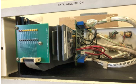
Figure 3 – cRIO with interposer boards between cSeries and field harnesses
The work to design and build the signal conditioning custom electronics was split between Viewpoint and Amentum. Viewpoint did more design than build and handed over the schematics and Gerber files to Amentum so they could manage the builds while also being able to make modifications to the boards as needed.
Benefits
Amentum wanted an engineering firm that was willing to work along side them as a partner. Joint discussions about architecture and design led to a collaborative development effort where Amentum benefited from Viewpoint’s extensive expertise and guidance on LabVIEW architectural implementation and FPGA coding style.
The main outcomes were:
- As a partner of the team, Viewpoint acted as staff augmentation by providing experienced engineers with technical capabilities that Amentum initially lacked.
- This team approach delivered a stronger product to the end-customer more quickly than either of us could do alone.
- The combination of Viewpoint’s and Amentum’s experience reduced the amount of reverse engineering needed due to the lack of firm requirements.
- Reduction of electronics obsolescence by using software-centric FPGA-based functionality. Recompiled LabVIEW FPGA could target future boards models.
- Increased software-based functionality simplifies future updates and modifications.
- Decrease in number of parts leading to simpler maintenance.
- Lower wattage consumed eliminated need for an anticipated HVAC upgrade.
- Cybersecurity concerns were reduced by using Linux-based systems and FPGA coding.
System Overview
Using software to emulate the old hardware was a critical success factor. Since the requirements were not 100% solid at the start of the project, some field-testing was required for final verification and validation. The flexibility of the software approach eased modifications and tweaks as development progressed. A hardware-only solution would have necessitated difficult and costly changes. For example, some of the changes occurred very near the final deployment after the system was finally connected to an actual unit in the field.
| SOFTWARE FUNCTIONS |
|---|
| Emulate original discrete logic functions via FPGAs |
| Emulate original analog signal I/O |
| Overall system control via Linux PC |
| Maintain the same user experience as existed before |
| Modern application architecture for simpler maintenance |
| HARDWARE USED |
|---|
| NI cRIO chassis with various cSeries modules |
| NI PXIe chassis with FPGA modules to handle all the analog and digital I/O via a combination of multifunction and digital-only cards |
| Custom PCBs for signal conditioning and connectivity |

Multi-deployment Remote Online Condition Monitoring for Rotating Machinery – Case Study

Multi-deployment Remote Online Condition Monitoring for Rotating Machinery
Reciprocating Compressors & Balance of Plant Continuous Monitoring
Client – Industrial Manufacturer of Rotating Equipment
Challenge
When these machines go down, it is expensive for the client, both monetarily and for their reputation. The client wanted a way to monitor these assets to catch potential failures before they become catastrophic. Many times, the machine shuts down and it is not known if it shut down for an electrical transient on a signal or a truly problematic rise in vibration, pressure, or temperature. Taking the asset offline to investigate can take weeks, so often it is turned back on without knowing if the problem will get worse or if was a glitch. Long term, the client’s goal is to gather enough data to be able to predict machine failures before they happen so they can plan their outages.
Solution
The solution to this problem was a remote online monitoring system utilizing off-the-shelf hardware. It has plans for deployment in dozens more over the coming months and years. Data is usually accessed remotely by a centralized team of data analysts. (Occasional lack of connectivity requires data to be transferred via sneakernet).
Benefits
- Frequent assessment of assets to distinguish anomalies from failures requiring maintenance
- Data being collected to enable the potential for future predictive maintenance
- Remote monitoring anywhere in the world
- Flexible monitoring configuration capabilities to accommodate a variety of deployed custom asset configurations
System Overview
The online monitoring system was developed utilizing custom software and off-the-shelf hardware. The software was developed by Viewpoint, and the hardware was selected by both the client and Viewpoint together as a team. The hardware utilized is an NI cRIO combined with one or more NI cDAQs per asset (including balance of plant equipment). TSN (Time-Sensitive Networking) allowed synchronous channels across multiple cDAQs.
The online monitoring system captures data 24/7, and every sample is used in trigger analysis, so no events are missed. When a signal trips a configured trigger level, a file is captured using pre- and post-trigger data. Notification emails are sent upon completion of each of these capture files. There are several trigger types.
Channels can be configured as several different types (accelerometer, tachometer, encoder, proximeter, pressure, temperature, voltage, current), and any number of channels can be configured up to a theoretical limit of 300 channels of input data, and most C Series modules can be used to capture analog data.
Inputs monitored:
- Tachometer
- Encoder
- Vibration
- Proximeter
- Accelerometer
- Pressure
- Temperature
- Voltage
- Current
| SOFTWARE FUNCTIONS |
|---|
| Continuous signal monitoring |
| Data capture and email notification on configurable condition triggering |
| Configurable measurement channels |
| HARDWARE USED |
|---|
| NI cRIO |
| NI cDAQ |
| NI C Series Digital Module |
| NI C Series Voltage Input Module |
| NI C Series Sound and Vibration Input Module |
| NI C Series Temperature Input Module |
| INTERFACES / PROTOCOLS |
|---|
| TCP |
| USB |
| FTP |
| SSH |
Online Monitoring of Industrial Equipment using NI CompactRIO
Online Monitoring of Industrial Equipment using NI CompactRIO
Improving Maintenance of expensive industrial equipment
Client – Large Industrial Equipment Manufacturer
Challenge
The maintenance of the equipment was not always done at the prescribed intervals because the cost of shutting down the plant is significant. This sometimes resulted in an equipment failure. This particular application is for equipment/machinery in the energy/power industry (a generator).
Solution
The online monitoring system monitors a particular parameter of interest to send warnings and alarms to the control room so that the operators know when maintenance needs to be performed on the particular part of interest. This system has been installed in multiple plants.
Benefits
- Enables condition-influenced maintenance intervals vs periodic intervals
- Reduces probability of catastrophic failure by providing warning indicator
System Overview
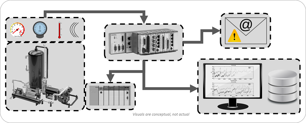
The system monitors the generator collector health. NI-based data acquisition hardware acquires the signal of interest, logs the raw data, processes the parameter of interest, and triggers/sends warnings and alarms to the control room. LabVIEW FPGA was used for analog and digital IO and a sensor check. LabVIEW Real Time was used for the calculation, data logging, serving data to the HMI and alarm/warning checking.
| SOFTWARE FUNCTIONS |
|---|
| Touchscreen GUI for data/alarm display and system configuration |
| Data logging |
| Signal processing and alarming |
| HARDWARE USED (selected by customer) |
|---|
| NI cRIO |
| NI Touch Panel Computer |
| Multiple NI C Series Modules |
| INTERFACES / PROTOCOLS |
|---|
| TCP/IP |
*- images are representative, not actual
Endurance Tester for Mission-Critical Mechanical Component using NI cRIO
Endurance Tester for Mission-Critical Mechanical Aerospace Component using NI cRIO
Ability to run tests unattended and overnight reduces operator labor and compresses test schedules
Client – Major Aerospace Component Supplier / Manufacturer
Challenge
The client had an older VB & PLC-based aerospace test bench in place already, but it was obsolete. A new endurance test bench needed to be developed to validate prototyped components (in this case, aircraft & aerospace bearings). Many of the prototypes are one-off, so it was important that the test system not destroy the component.
Solution
A new endurance test bench was developed to validate prototyped aerospace components. The test bench can be configured for automatic shutdowns so as not to destroy the component under test in the event of unexpected performance of electro-mechanical subsystem components. The updated endurance tester supports product validation by allowing the product to run under various test conditions (e.g. speed, load, oil flow, temperature) and collecting data for analysis.
Viewpoint developed the software and selected the NI hardware (other hardware was selected by the client).
Benefits
System Overview
The updated cRIO-based endurance tester incorporates configurable profiles, data logging, and automatic shutdown to allow for safer extended validation testing. LabVIEW FPGA and LabVIEW RT were used together to interface with the test hardware sensors and controls. LabVIEW as used create the HMI for the test system.
| SOFTWARE FUNCTIONS |
|---|
| Closed loop control of bearing test oil flow |
| Axial load control |
| Driver for Emerson VFD |
| E-Stop and safety management (shutdowns based on alarm limits) |
| Data collection – temperature, pressure, flow, vibration, frequency |
| Operator/Diagnostic GUI for control of system |
| HARDWARE USED |
|---|
| NI CompactRIO (cRIO) |
| NI C Series Current Input Module |
| NI C Series Voltage Input Module |
| NI C Series Temperature Input Module |
| NI C Series Current Output Module |
| NI C Series Analog Input Module |
| NI C Series Sound and Vibration Input Module |
| NI C Series Digital Module |
| Emerson VFD (Variable Frequency Drive) |
| INTERFACES / PROTOCOLS |
|---|
| TCP/IP |
| TCP Modbus |
Endurance Tester using NI cRIO
Endurance Tester using NI cRIO
Multiple International Deployments Helps Prove Product Meets Spec.
Each endurance test can run upwards of 6 months.

Client: Major Automotive Component Supplier
Challenge
A new endurance test system was developed to give more precision in the control setpoint. This additional precision enabled potential clients to review the product performance in real-life situations. Each endurance test can run upwards of 6 months.
Solution
The updated endurance tester supports product validation by providing the desired parameter control method, allowing the client to prove more obviously that their part met the stated specification.
Viewpoint developed the software and selected the NI hardware for the first unit. The client is now deploying copies of this system to multiple international manufacturing plants.
Benefits
- Able to prove meeting a particular product specification of interest
- Closed loop parameter control
- Data collection
- Configurable Alarms
- Emergency shutdown functionality
System Overview
The cRIO-based endurance tester provides closed loop control, data collection, and alarming with controlled and emergency shutdown functions. The operator can manually configure a test or load a saved configuration. After a manual operator check to make sure the setup is operating correctly, a successful test will run its full duration and stop on its own.
| SOFTWARE FUNCTIONS |
|---|
| Touch PC interface / GUI |
| Closed loop parameter control |
| Data collection |
| Controlled & emergency shutdown |
| Alarming |
| HARDWARE USED |
|---|
| NI CompactRIO |
| NI analog input cSeries module |
| NI analog output cSeries module |
| NI digital input cSeries module |
| NI digital output cSeries module |
| INTERFACES / PROTOCOLS |
|---|
| TCP |

Product Validation & Production Test System – For complex Mission-critical sub-system
Product Validation & Production Test System – For complex Mission-critical sub-system
Client
Ensign-Bickford Aerospace & Defense

Upgrade reduces per unit test time by ~40% and improves reliability of software
Challenge
The customer needed to upgrade their existing test system. Their old test system was very manual:
- It did not provide ability for unattended operation
- The thermal control had to be set manually
- They wanted to do less manual review of the data
The client develops mission-critical products, so there’s a desire to reduce manual operations because they have to explain any anomalies, and manual operations are typically more error-prone. They needed repeatable results that they could trust.
Solution
Viewpoint developed a new test system that utilized new hardware and software, augmented by existing low level hardware and firmware. The test system was developed to perform both functional test for production and environmental testing, and was designed to handle up to 4 DUTs at once. The test system utilizes the StepWise test executive software with custom test steps, which allowed the client to create their own highly configurable test sequences. The system was developed in two phases, with the second phase adding support for a FPGA expansion backplane (NI CompactRIO chassis) in order to provide future capability for bringing some of the microcontroller sequence activity into the NI space. In addition, the previous version had a mix of serial, TTL, and USB instrumentation, which was not as robust as Ethernet based instrumentation. Phase II involved upgrading to all Ethernet based instrumentation, and did away with the original test system’s many manual toggle switches that could be used instead of the programmable mode through the SW.
Benefits
- ~40% test time reduction per unit
- ~25% reduction in anomalies that needed to be justified
- ~500 manhours saved in test execution
System Overview
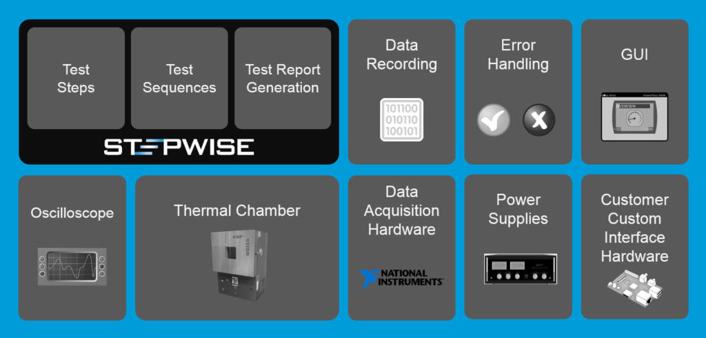
| Software Functions |
|---|
| Test sequencing |
| Test report generation |
| Data recording/logging |
| Error handling |
| Test GUI |
| Oscilloscope interface |
| Thermal chamber interface |
| Power supply interface |
| External custom hardware interface |
Industrial Equipment Remote Online Condition Monitoring

Industrial Equipment Remote Online Condition Monitoring
Using NI CompactRIO
Client
A manufacturer of large industrial mission-critical equipment in the electrical energy / power industry.
Challenge
Our client had three main goals in mind. They wanted to:
- Decrease unanticipated downtime and maintenance expenses
- Provide a more complete picture of machine operation and state
- Improve equipment usage tracking.
Solution
The solution is a multi-node (i.e. multi-site) remote monitoring system that utilizes an NI cRIO-based controller with customized NI InsightCM monitoring software.
Benefits
- Monitors vibration signals to predict expensive equipment failures
- Monitors current machine state via Modbus from other equipment in the system, including the primary system controller
- Provides alerts via email when any designated parameter is out of range
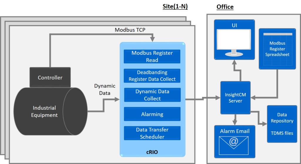
System Overview
The remote monitoring system monitors equipment condition by taking several vibration signal measurements along with reading over 500 Modbus registers. Local InsightCM vibration analysis on the cRIO extracts key features from the accelerometer data. Limit detection is run on these features and other equipment state and alarms are triggered when data is out of bounds. Information collected at multiple sites is sent to a central location either at periodic intervals or based on an alarm condition.
| SOFTWARE |
|---|
| NI InsightCM software |
| Modbus register configuration & reading |
| Dead banding-style register data collection to decrease amount of data captured and transferred |
| Dynamic signal data capture |
| Alarming detection |
| Data transfer scheduling |
| Semi-real-time alarm channel display |
| HARDWARE USED |
|---|
| NI cRIO |
| NI IEPE Analog Input Module |
| Microsoft Windows Server to host the NI InsightCM server software |
| INTERFACES / PROTOCOLS |
|---|
| Modbus TCP |
| Ethernet TCP/IP |
Industrial Embedded Control for Advanced Manufacturing
Industrial Embedded Control for Advanced Manufacturing
Energy & Aerospace components manufacturing
Client – Automated Dynamics
Challenge
Utilize laser energy to heat thermoplastic or thermoset composite during an automated fiber placement manufacturing process.
Solution
Starting from a proof of concept developed by Automated Dynamics, Viewpoint developed the industrial embedded laser controller software for the automated fiber placement manufacturing equipment. The hardware utilized was an off-the-shelf CompactRIO controller from National Instruments.
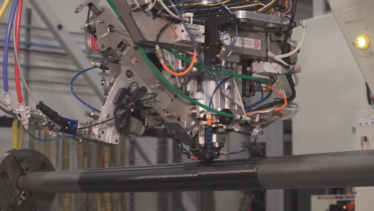
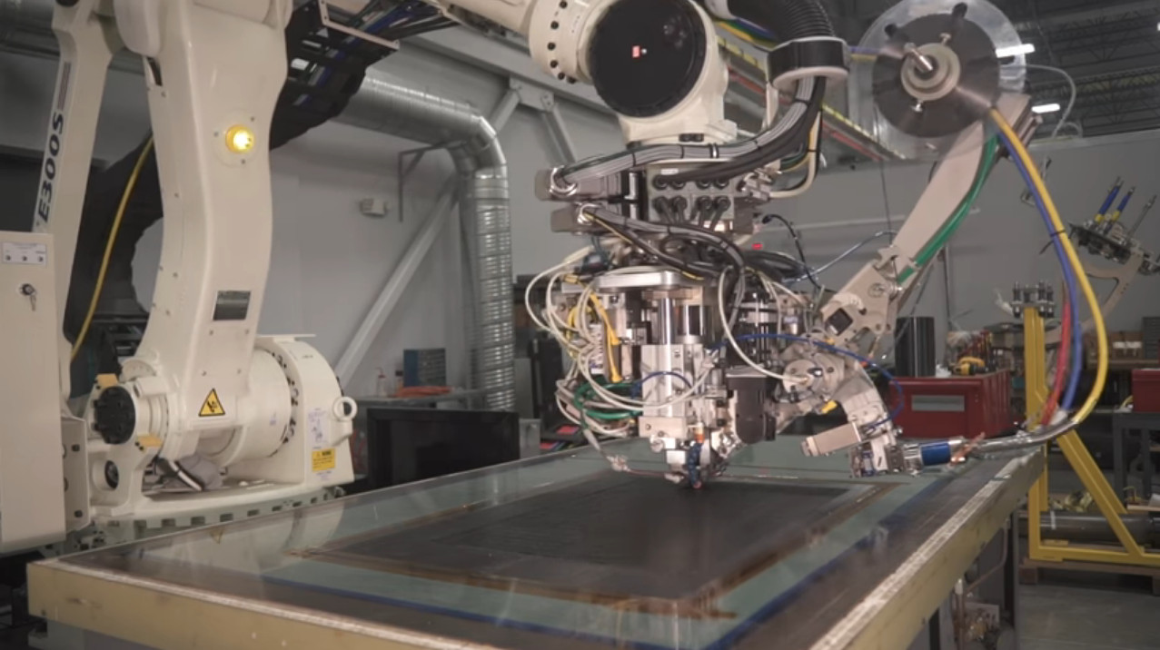
Benefits
- High-speed temperature control
System Overview
See it in action here:
Industrial Embedded Monitoring & Control of Manufacturing Equipment

Industrial Embedded Monitoring & Control of Manufacturing Equipment
Adding Closed-loop Precision Control to Manufacturing Process with multiple international plant deployments
Client – Quantum Engineered Products Inc.
![]()
Challenge
Quantum produces manufacturing machine components that are used in the glass bottle forming process. Specifically, they supply plunger mechanisms that are used in the initial blank side formation of the glass bottle.
The engineers at Quantum recognized that they had an opportunity to improve the bottle formation process by adding position sensing to their plunger mechanisms. The ability to sense and record plunger positions would enable machine operators to monitor the travel of the Quantum plunger into the molten glass gob within the blank side mold, identify and diagnose potential hardware problems, and provide real-time feedback that could be used to better control the process.
Quantum needed a partner to implement real-time control and monitoring of the bottle forming process and selected Viewpoint for the task.
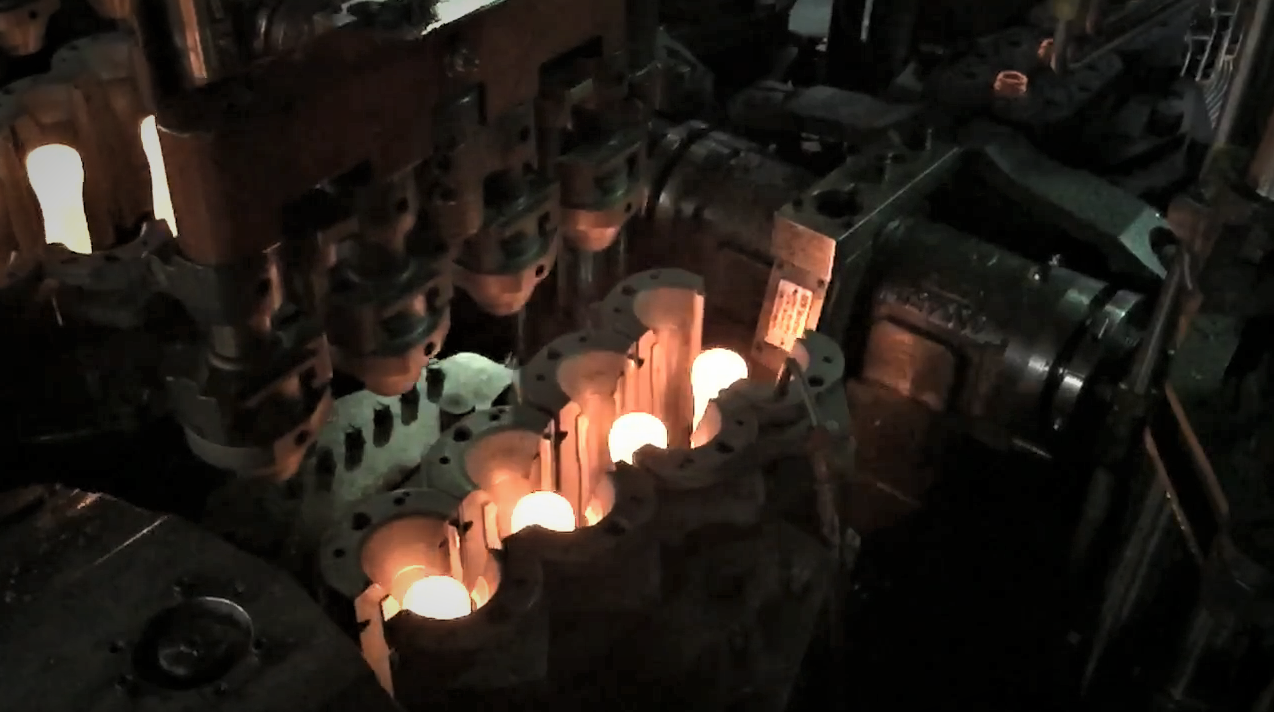
Solution
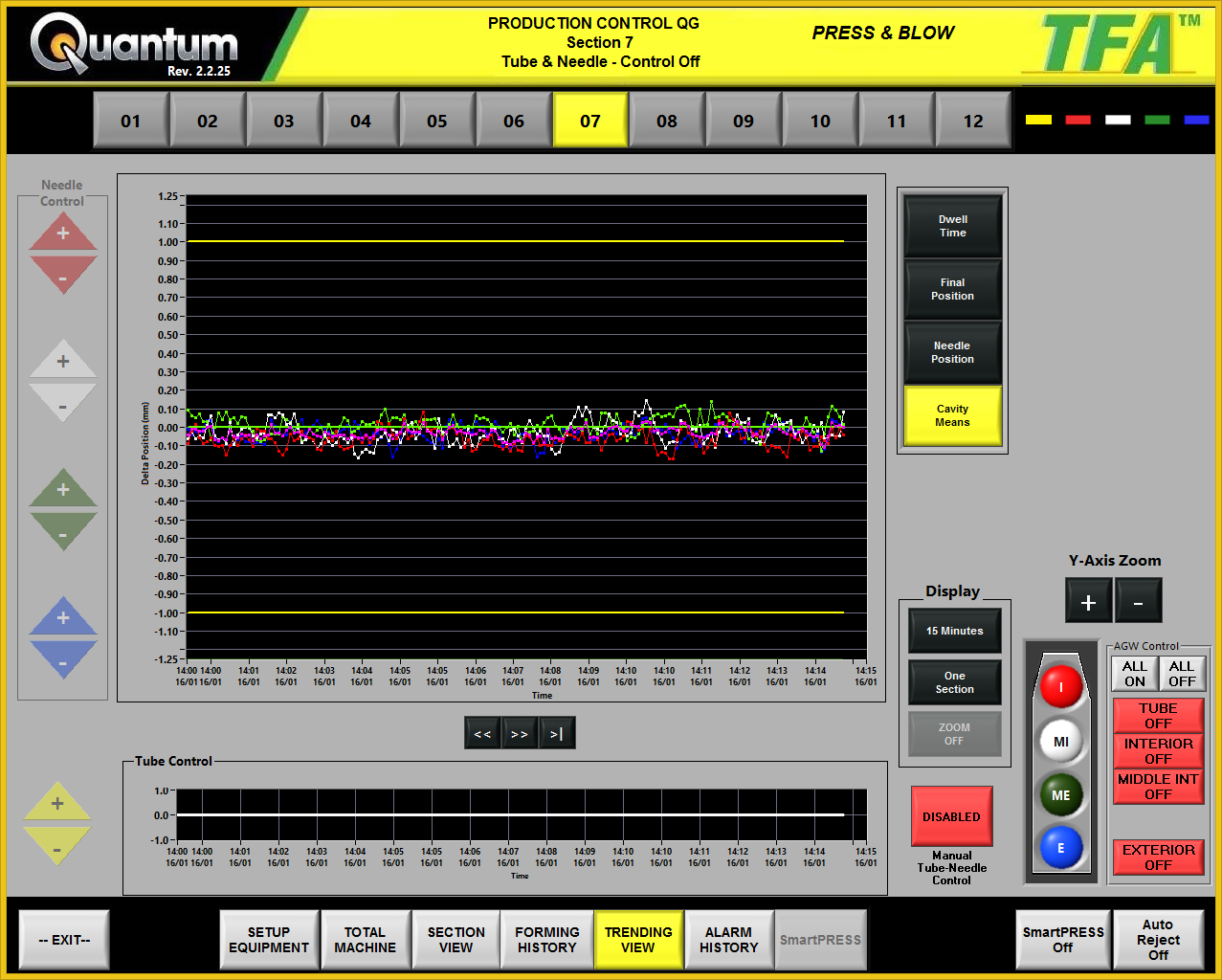
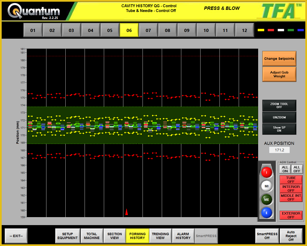
Viewpoint developed custom monitoring and control software that runs on off-the-shelf hardware. The software developed for Quantum is called TFA™ (Total Forming Analysis). The TFA™ software is a process monitor and control system for the hot side of the bottle forming process.
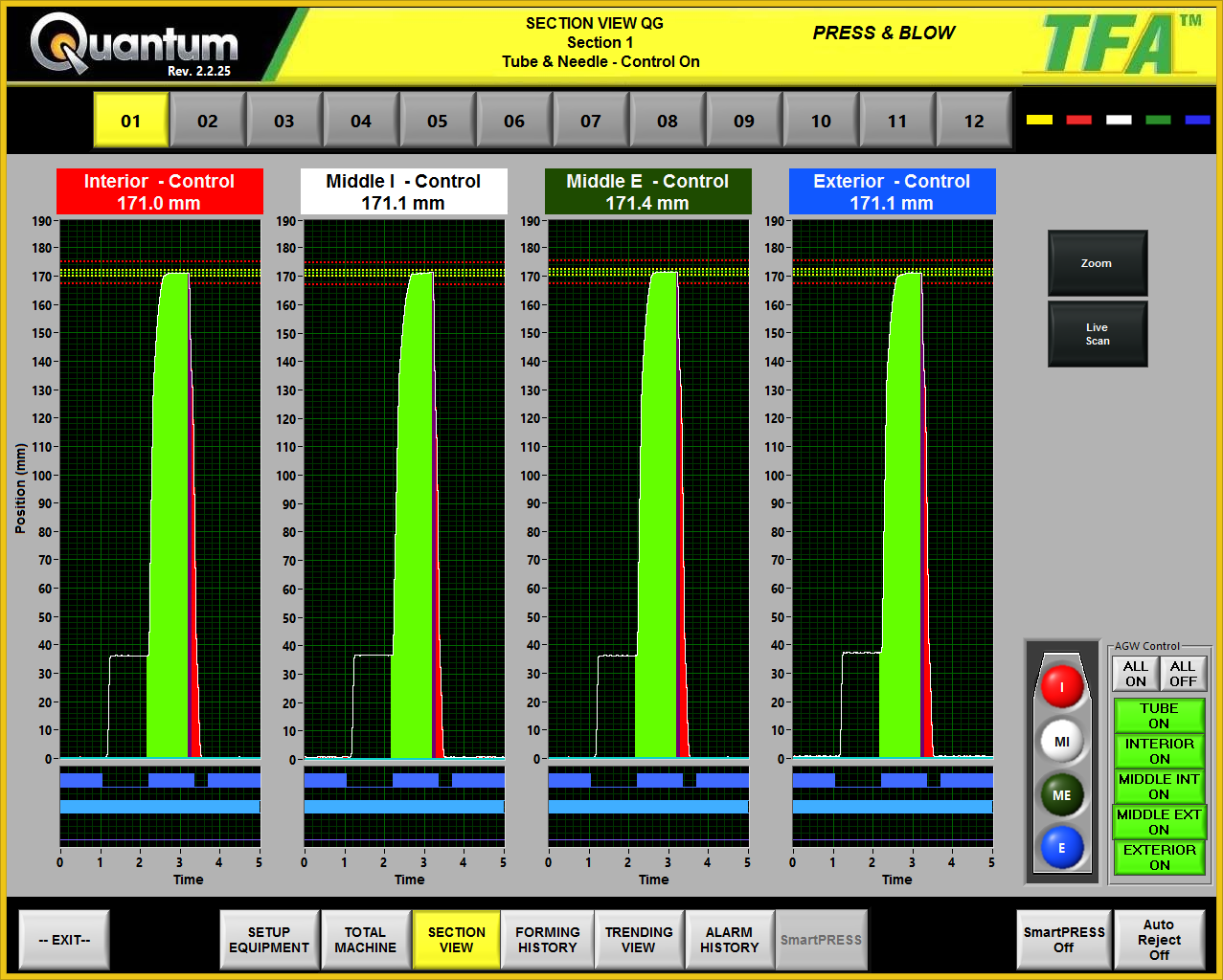
The software takes position information from the plungers Quantum supplies to the factories to show the travel of the tube during the forming process. The software measures key aspects of the plunger position profile such as initial plunger load position, final position, and dwell time at the final position. When these measurements are found to be out of tolerance, the software communicates with the machine auto-reject system to ensure that bad bottles are removed from the system.
Moreover, the final plunger position is used as feedback to do closed loop control of the glass gob weight, controlling glass feeder tube height and/or needle heights to change the glass gob weight. This allows for precise control of container weight, making the most efficient use of raw materials while ensuring container quality.
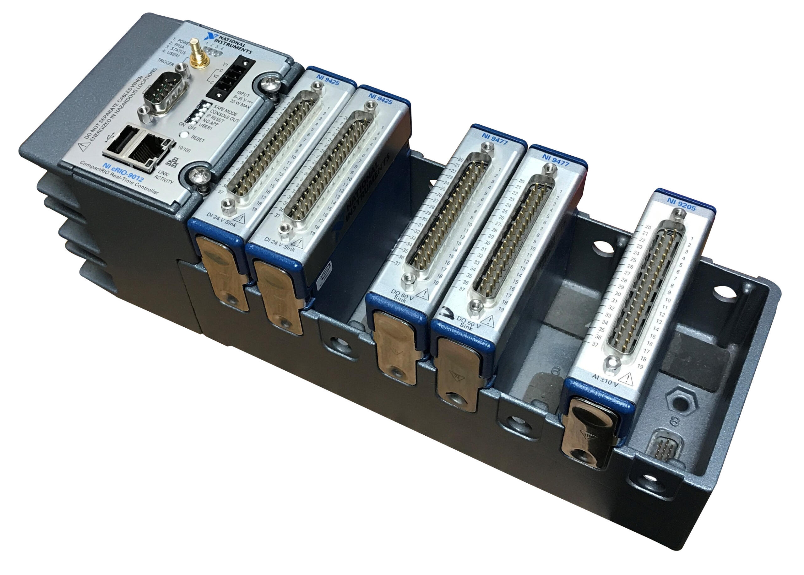
To accommodate multiple end-customer-driven hardware configurations, the off-the-shelf hardware selected was based on the National Instruments CompactRIO family of chassis to enable configuration of various input/output signal requirements.
For the end result, check out one of the machines running TFA™ in action:
Benefits
Hardware Customization Flexibility – every one of Quantum’s customers wants something either a little or a lot different with their particular instance of the system. Using modular hardware allowed for swapping of I/O hardware.
Quick Response to Software Feature Requests – Quantum and Viewpoint were in constant communication to be able to implement new features and tweaks on fairly short notice (generally within a couple of weeks).
On-Site Support – Viewpoint engineers travel to Quantum’s customer sites with them as a team upon request.
System Overview
The embedded process monitoring and control system consists of custom process monitoring and control software that runs on off-the-shelf hardware.
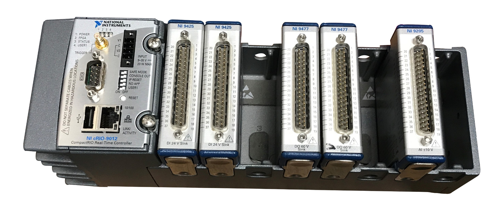
| NOMINAL HARDWARE |
|---|
| NI 9148 Ethernet expansion chassis |
| NI 9201 module for AI |
| NI 9425 module for DI |
| NI 9476 module for DO |
| SOFTWARE FUNCTIONS |
|---|
| Data Acquisition and Processing |
| Waveform Calculations (eg. final position and dwell time) |
| Final Position control loop |
| Real-time per cavity plunger position graphs |
| Process trend graphs |
| Forming history graphs, showing a packet of the last forty final positions per cavity |
| Limits definition screens |
| System health summary, fault monitoring and auto-reject configuration |
| Job configuration |
| Plunger sensor calibration |
| COMMUNICATION INTERFACES |
|---|
| Gb Ethernet communication with the DAQ devices (NI 9148 chassis) |
| TCP/IP Modbus communication with Schneider Electric motors for feeder tube and/or needle control |
TFA™ is a registered trademark of Quantum Engineered Products, Inc.
Industrial Embedded – Using a cRIO for Rapid proof-of-concept Prototyping | FPGA-based motor control & RT-based loop control
Industrial Embedded – Using a cRIO for Rapid proof-of-concept Prototyping
FPGA-based motor control & RT-based loop control.
The NI cRIO platform allowed for rapid development/test cycles. There was as little as ~1.5 hours between a software change and a test.

Challenge
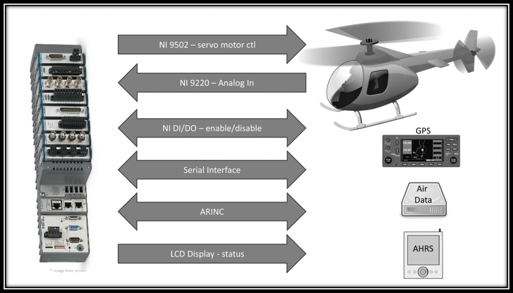
This was a rapid proof-of-concept prototyping effort to quickly determine feasibility of auto-pilot flight.
Solution
The cRIO-based controller was able to allow the helicopter to auto-pilot routed waypoints.
Benefits
The NI cRIO platform allowed for rapid development/test cycles. There was as little as ~an hour and a half time between a software change and flight test. Code updates could be flight tested in the morning, updated over lunch, tested again in the afternoon, updated one more time at night, and flown again the next morning. This allowed for rapid development of control laws.
System Overview
The core system functionality consists of:
- resolver-based BLDC motor control
- position loop control
- vehicle dynamics control
- and flight logging.
Vehicle dynamics control and position control lived on the RT processor, while motor control and critical high-speed processing lived on the FPGA.
Production Test of Large Uninterruptible Power Supplies
Portable Test Stands for Production Test of Large Uninterruptible Power Supplies
Manufacturing Test of UPS Units Designed for Data Center Backup Power
Client: A major manufacturer of data-critical three-phase uninterruptable power supplies
Challenge
A major manufacturer of very large three-phase uninterruptible power supplies (UPSs) needed better measurement, analysis, and report generation capabilities. Their clients used these UPSs on mission critical equipment, such as data warehouse server farms, communications equipment, and so one. Existing testing procedures used equipment that did not allow for complete simultaneous coverage of all sections of a UPS unit, from input to output. Our client wanted a better understanding of the signals on each of the three phases at various locations within the UPS, especially when power sources were switched or faults were induced. The physical extent of these UPSs could be large, especially when several were combined. Having movable test stands would make access to these test locations less cumbersome.
Also, in the prior test procedure, factory acceptance reports were manually assembled for our client’s end-customers, delaying the final sign-off. Finally, since the end-customer might want to run a specially configured test or run a series of tests in a different sequence than some other end-customer, our client wanted to be able to rerun certain types of tests or run tests in a customer-specific order. Thus, the test sequencing needed to be flexible and editable, possibly on the fly.
Finally, synchronization between the data collection on all signals was critical to assess functionality, since all 3-phases of the UPS output needed to be in the proper timing relationship.
Solution
At a high-level, the majority of testing a UPS relies on knowing the reaction of the UPS to changes on the input side (such as a grid power outage) and changes on the output side (such as an immediate heavy load). Thus, many of the tests performed on a UPS deal with power quality measurements, such as defined by IEEE 519 or IEC 61000 series standards, which cover both continuous and transient operation. The StepWise test execution platform was utilized to allow the customer to develop arbitrary test sequences using the application specific test steps developed for the program.
Our solution used a cRIO to measure both current and voltage from each leg of the 3-phase power (and neutral) by using appropriate cSeries modules connected to various voltage and current test points within the UPS. The cRIO had enough slots to allow a single cRIO to measure a single UPS. This cRIO and connection points were housed in a movable test stand (see image above).
Assessment of continuous operation mainly reviewed the UPS output power quality. Here, it was important to know the amplitude and phase of each leg of the 3-phase power. Synchronous data acquisition between all voltages and current channels was needed for proper timing alignment of collected data points.
Assessment of transient operation was often a review of power ripple and recovery time. For example, in the event of grid power loss, a UPS would switch over to backup power, with the result being a small transient created on the output of the UPS. Again, the voltages and currents needed to be collected synchronously to assure that event timing was aligned.
For increased power capacity, the UPSs could be connected in parallel. When ganged together, the continuous and transient behavior of each UPS needed to be compared to the others, in order to capture the behavior of the entire combined system. Consequently, each cRIO (one per UPS) had to share a clock to enable synchronous data collection across all cRIOs. A timing and synchronization module was placed into each cRIO chassis with one cRIO acting as the master clock source and the others being slaved to that clock. Several test stands were then connected together to share this clock to achieve the simultaneous sampling across all test stands.
The overall test system architecture has a master PC communicating with each cRIO. Each cRIO was placed in certain activity states by the master PC, such as “arm for measurement”, “transfer collected data”, and “respond with system health”. This arrangement enables the number of cRIO-based test stands to shrink or grow depending on the number of UPSs being testing in parallel.
Results
The test system connected the timing module in each cRIO-based test stand in a daisy-chained configuration, leading to data sampling synchronization error of less than 100 ns between all cRIOs, which translates to about +/-0.001 degree phase error for 60 Hz power signals. This timing synchronization was more than sufficient to analyze the collected waveform data for power quality and transient structure.
LabVIEW was used to create various configurable test steps that could be executed in random order as well as in an automated sequential manner. Our client was thus able to test a UPS in a predefined manner as well as react rapidly to queries from their customer when they were viewing a factory run-off test. For example, the customer might ask to re-run the same test several times in a row to validate consistent responses.
Each type of test included automated analysis routines that numerically calculated the relevant parameters against which the UPS was being checked. Not only was this automated calculation faster, but it reduced mistakes and improved reproducibility as compared to the previous post-testing partially manual calculations.
Data from all tests, even repeated ones, on a given UPS were archived for quality control purposes and made a part of the device history for that UPS.
Finally, the report generation capability built into this test system was far superior to the previous methodology by allowing our client to hand their customer a professional report package practically immediately the testing was complete. Customer satisfaction was improved substantially with this state-of-the-art test system.
Condition Monitoring – Improving the Uptime of Industrial Equipment

Condition Monitoring – Improving the Uptime of Industrial Equipment
Monitoring the Health of Industrial Equipment
Client: A large industrial company that uses industrial-grade compressors.
Challenge
- Increase awareness of potentially harmful operating conditions.
- Record detailed data upon event detection.
- Reduce unnecessary equipment shutdowns due to spurious vibration transients.
Solution
We utilized an off-the-shelf controller (NI cRIO) combined with custom software in order to augment and create the first system with ~2 man-months of effort. This solution has been installed in several facilities and is projected to be installed in hundreds of facilities around the world.
Benefits
- Send alerts via email when potentially harmful operating conditions occur.
- Record detailed data upon event detection for failure analysis and predictive maintenance.
- Suppress spurious vibration transient signals to reduce unnecessary equipment shutdowns.
System Overview
Condition Monitoring for Electric Power Generation
Condition Monitoring for Electric Power Generation

Monitoring generator and turbine components of power generation equipment
The CompactRIO-based system has allowed for continuous monitoring, rather than just a periodic review of turbine and generator performance. In addition, by combining the FPGA and the RT processor in a physically small device, the solution has been able to ensure very fast data acquisition, data reduction, and sophisticated analysis.
Client: A multi-national power generation equipment manufacturer
Background
Continuous monitoring of power generation equipment can have a great impact on maintaining a reliable flow of power to consumers as well as alerting the power generation equipment operator to potential equipment damage if timely repairs are not made.
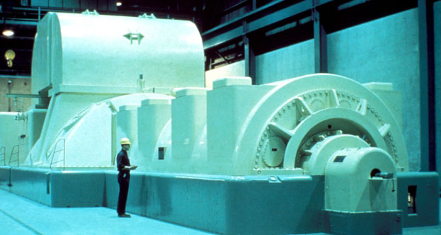
This case study will focus on two measurement systems utilized by a multi-national power generation equipment manufacturer to monitor the generator and turbine components of their power generation equipment.
The manufacturer’s systems needed relatively high-speed waveform sampling, well-suited to the National Instruments CompactRIO platform. Viewpoint Systems provided technical assistance in the development of these systems.
Challenges
The difference in the types of analyses and data rates of the measurement systems required a flexible yet capable hardware platform. Each system needed to work on a generator outputting 50 Hz AC or 60 Hz AC.
Viewpoint’s Solution
The CompactRIO platform and LabVIEW proved to be an excellent solution for the electric power generation condition monitoring system’s data acquisition and analysis needs. The small size and robustness of CompactRIO allowed the system to be placed at a preferred location. In both the flux probe and the blade tip timing, the CompactRIO FPGA could acquire and pre-process the data. The CompactRIO successfully managed – and continues to manage – all analysis, data archiving, and communication with a host PC.
In the case of the tip timing, the data rates were high enough that the detection of the tip location for each signal needed to be performed in the FPGA so that the real-time (RT) layer received a much-reduced data rate of tip locations. The RT processor was able to perform higher level analyses on these timings. Occasionally, a snapshot of a raw tip timing waveform could be passed to the RT processor for archiving and presentation to an engineer. However, due to the data bandwidth and processor loading of the CompactRIO, such snapshots must be infrequent.
For both systems, a master PC managed the operator user interface, long-term data collating, reporting, and archiving of files and statistics. Each CompactRIO connected to this master PC via a TCP/IP connection.
Results
The CompactRIO-based system has allowed for continuous monitoring, rather than just a periodic review of turbine and generator performance. In addition, by combining the FPGA and the RT processor in a physically small device, the solution has been able to ensure very fast data acquisition, data reduction, and sophisticated analysis. By deploying CompactRIO devices, the multi-national power generation equipment manufacturer achieved a cost-effective method of monitoring the power generation facility equipment, ensuring detection of operational issues quickly and easily.
Technical Highlights
Both measurement systems described required sampling rates greater than 10 kHz, restricting the use of traditional PLC-based data acquisition devices and requiring a programmable automation controller (PAC). Each system measured the performance by connecting to special sensors and associated signal conditioning, provided by our customer, such that the data acquisition equipment only needed to support ±10 V signals. Furthermore, each of these systems needed to push data to a master PC for data trending, result archiving, and operator display.
Despite the significant differences in the measurement types, Viewpoint Systems was able to utilize a common set of data acquisition, processing, and connectivity tools, based on the NI CompactRIO platform and LabVIEW, to monitor the system.
More information about each measurement system follows.
Flux Probe
The flux probe system looks for shorts in the windings of the generator. Each time a winding passes under the flux probe, the probe output increases. When a winding is shorted, the field created by the winding is reduced and detected as a lower amplitude output by the flux probe. The position of a shorted winding inside the generator can be located by measuring a key-phasor signal that pulses once per revolution and converting the timing offset of this weakened signal into an angular position. Both flux and key-phasor signals are measured at about 50 kS/s.
Figure 1 shows an example signal output by a flux probe. The local peaks are indicative of winding current. Automated analysis of the amplitudes of the flux signals can be challenging due to changing waveform shape as a function of generator load and severity of shorts.
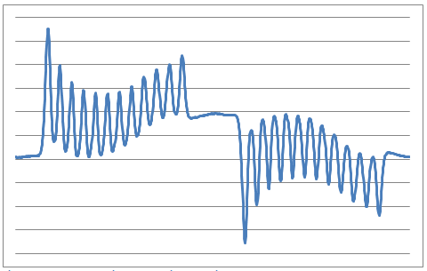
Figure 1 – Example flux signal over a single rotation
A good reference of the flux probe technique is described in the Iris Power Engineering article, “Continuous Automated Flux Monitoring for Turbine Generator Rotor Condition Assessment.”
Turbine Tip Timing
The turbine tip timing system looks for displacement of each turbine blade tip from nominal position. At slow rotational speeds, the spacing between each tip closely follows the uniform blade spacing. At higher speeds, vibrations and resonances can make the blade tips wobble slightly, causing small deviations in the timing of the tip passing by a sensor.
A special proximity sensor detects the tip of the turbine blade, and can be based on optical, eddy-current, microwave, and other techniques. Any positional deviations of a tip from nominal give indications about the mechanical forces on the blade as well as compliance of the blade to those forces as the blade ages. Specifically, each blade has natural resonances and compliance, both of which can change if the blade cracks.
A turbine typically contains several stages and each stage contains many blades. See Figure 2 below for an example. The number of tip sensors per stage is variable; if blade twist is measured, at least two sensors are oriented perpendicular to the rotation direction. Also, the acquisition rate from each sensor is fast. For example, consider a stage with 60 blades, the width of each blade occupying about 1/10 the space between adjacent blades, and a generator running at 3600 RPM (60 Hz). The tip sensor would detect a pulse every 1/3600 s, lasting for less than about 1/36000 s, as the blades passed by. Accurate location of the pulse peak or zero-crossing then requires sample rates over 100 kS/s. Because multiple sensors are typically used, tip timing measurement systems can easily generate 10s of MBs of data per second.
Figure 2 – Example generator turbine blades
A good reference for the tip timing technique is described in the article by ITWL Air Force Institute of Technology – Poland, “Application of Blade-Tip Sensors to Blade-Vibration Monitoring in Gas Turbines.”
Industrial Embedded – Industrial Equipment Control

Industrial Embedded – Equipment Control – VAR Compensator
Keeping the Electrical Grid Healthy with VAR Compensation
Modular Embedded System Shortens Development Time and Reduces Risk in Static VAR Compensation System
Client: T-Star Engineering & Technical Services: A manufacturer of electrical power delivery equipment.
Background
The U.S. power grid is a large electrical circuit that, although has some amount of isolation between loads, is certainly interconnected at drop points, which is what customers care about most.
SVCs are generally worth considering in scenarios where large electric motors are being utilized (e.g. mills, recycling plants, mines). Problems such as voltage sag, voltage flicker, and current harmonics can cause reduced motor torque, lights to flicker, and equipment damage.
Challenge
T-Star has significant domain expertise in stabilizing medium voltage power systems. Viewpoint has significant domain expertise in the realm of measurement and control systems. The team at T-Star needed a well-supported intelligent device for their new generation Static VAR Compensator (SVC). They wanted a highly reliable solution that had minimized the time-to-market and a highly predictable future migration path for higher volume production. They also needed multi-channel precision timing, and high speed logging in a device certified for operation in dirty industrial environments.
Solution
Viewpoint was asked to develop the controller for T-Star’s Static VAR Compensator (SVC) using a carefully constructed specification. The chosen controller platform is a National Instruments (NI) Compact RIO due to its modular feature set, networking capabilities, and associated supportability and quality that comes with an industrial-grade off-the-shelf controller. T-Star and Viewpoint have made very complementary GSD (Get Stuff Done) teammates.
As the grid gains intelligence, this class of smart/dynamic power quality system will likely become more critical.
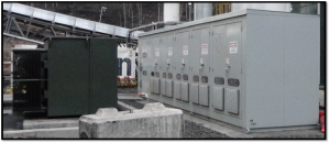
Cabinets for an SVC located at a remote mine in British Columbia
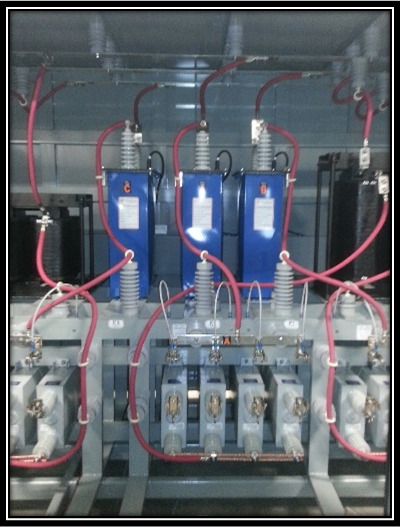
Inside an SVC
Benefits
- The platform supports other future configurations that are outside the phase one scope of this project.
- Time-to-market is critical for T-Star. The initial proof of concept was completed in weeks.
- The Linux-based OS, well known in the embedded community, provides a rich ecosystem for enhanced usability (e.g. network stack), and real-time operation.
- Secure access through VPN with built-in firewall and user account control and permissions allows for remote diagnosis, health monitoring, and gathering of online information.
- An FPGA allows for deterministic timing and parallel processing.
- With COTS hardware, future upgrades are simplified with code base reuse and recompiling for new hardware.
- The NI platform provides a migration path to a lower-cost solution once hardware configurations are locked down and production volumes increase above a certain level.
- The NI control hardware is certified (certifications in the domains of CE, FCC, UL, etc.) for marine applications and other challenging environments.
System Overview
The SVC tunes a highly inductive load by dynamically injecting a variable amount of capacitance due to the measured load. Voltage and current sensors feed a series of control algorithms which determine the voltage and current imbalance in order to inject the appropriate amount of capacitance into the power system. This algorithm acts on a cycle-by-cycle basis. The figure below illustrates the system makeup.
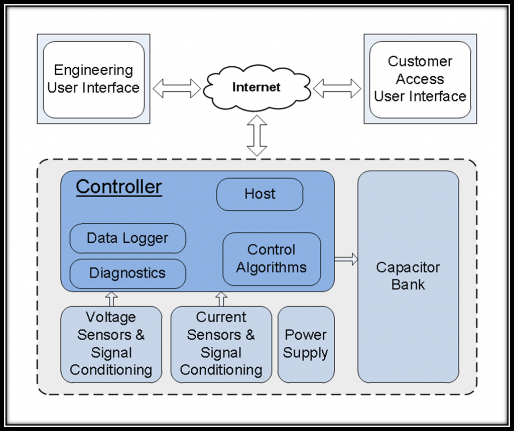
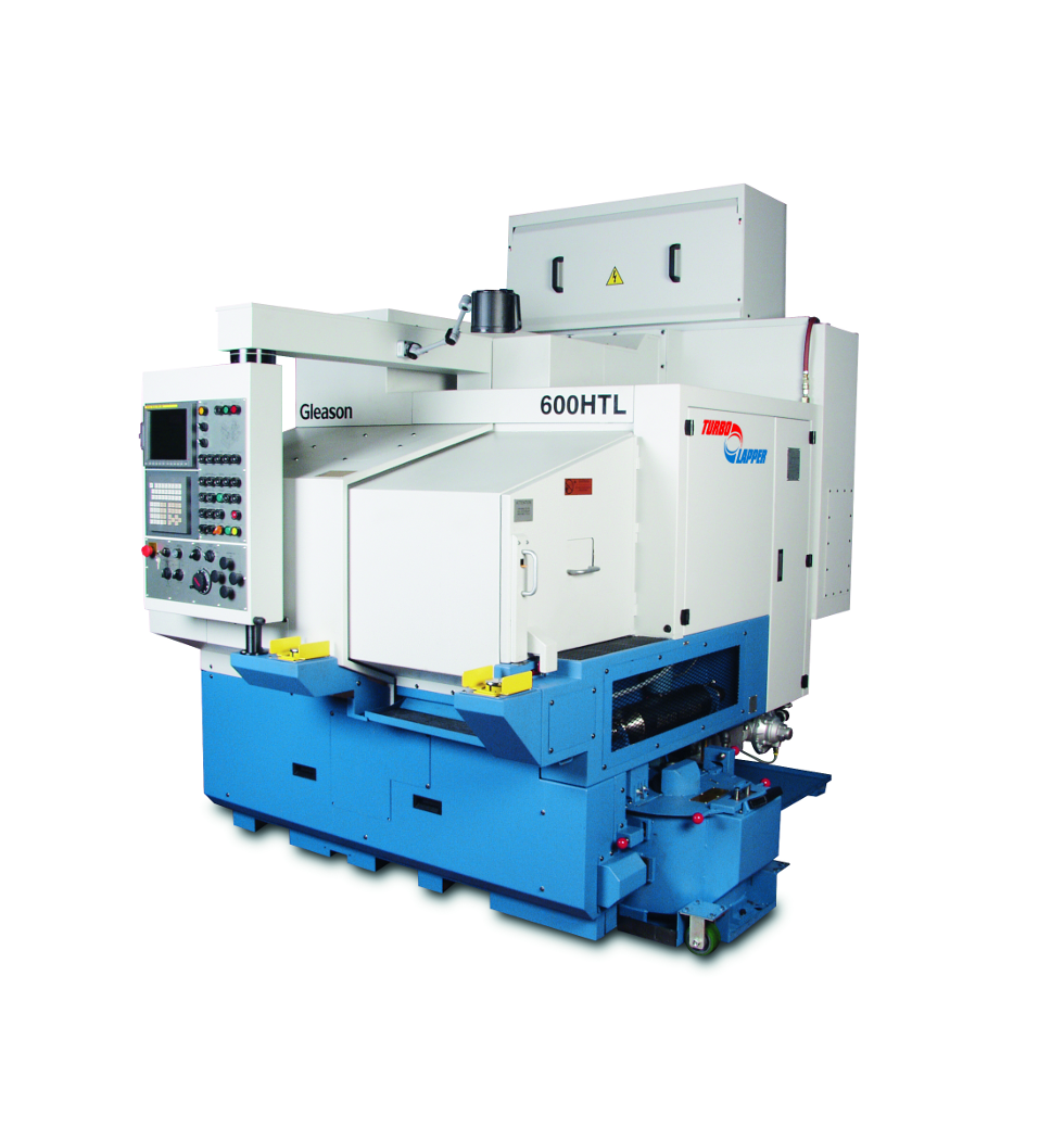
Embedded Control for Industrial Machine – Gear Lapper

Embedded Control for Industrial Machine – Gear Lapping
VIEWPOINT SYSTEMS IMPROVES GEAR FINISHING USING REAL-TIME EMBEDDED CONTROL SYSTEM WITH NI RIO HARDWARE.
THE GLEASON WORKS’ BEST-IN-CLASS GEAR MANUFACTURING SYSTEMS NOW PRODUCE HIGHER QUALITY GEARS IN 30% LESS TIME
With the embedded control system that Viewpoint created using NI
RIO hardware and LabVIEW FPGA, our customers can increase gear
quality and save cost at the same time.
Challenge
The Gleason Works sought to create a dynamic, torque-controlled lapping solution with responsive, realtime feedback to create better quality gears and reduce cycle time for its gear lapping machines.
Solution
Viewpoint Systems provided system integration using NI RIO technology and LabVIEW FPGA code for real-time measurement and control.
Background
Gleason Corporation and The Gleason Works create the machines, tooling, processes, services, and technologies needed to produce the bevel and cylindrical gears found virtually everywhere – from automobiles and airplanes to trucks and tractors, and from giant wind turbines that can power a thousand homes to the lawn mowers and power tools found at these homes. Gear tooth surfaces and spacing are never perfectly machined, and consequently, noise and vibration are often present in applications where the gears are later used. Gears, after the typical heat treatment process, are commonly lapped or ground to smooth the gear teeth surfaces and improve operational characteristics. The goal of lapping is to reduce surface and tooth spacing deviations that may produce noisy gear sets.
Gleason machines lap gears in pairs, the mating gear and pinion members rotating together at a high speed with an abrasive lapping slurry applied. After machining and heat treatment, however, the spacing deviations that need to be lapped are at unknown locations on the gears and can show themselves as run-out (i.e., an off-center axis). To further complicate finding the deviations, the run-out is actually composed of multiple orders, likely making the run-out for each order different than the others.
One conventional approach to lapping employs machines with relatively high-inertia spindles to carry the gearset members. At moderate speeds, this configuration can somewhat reduce spacing errors during lapping, but is far from optimal in refining the tooth surfaces. Another approach employs at least one low-inertia spindle. This configuration can refine tooth surfaces well, but tends to increase spacing errors—especially at higher speeds. In both conventional cases, one spindle is operated in a simple constant torque command mode to control lapping force, but the critically important dynamic torque components are left to passive physics.
To get the best of both worlds, Gleason could no longer rely on passive physics, and turned to Viewpoint Systems to help develop and implement an embedded control system that could measure deviations in real-time and apply dynamic corrective torque.
Results
With this new, patent-pending system founded on embedded control and dynamic real-time process monitoring technologies, Gleason and Viewpoint bring exciting new capabilities to a worldwide and well-established gear finishing process. The unprecedented ability to improve gearset quality during lapping, and to do so at higher speeds provides a winning market proposition—one made possible by intelligent application of today’s leading-edge technologies. With its new solutions, Gleason gear manufacturing systems now produce higher quality gears in 30 percent less time. Throughout the process, Gleason appreciated Viewpoint’s expertise and synergy achieved when working together. More than just an implementer, Viewpoint’s experts worked alongside their own to develop new techniques and solutions in an agile and collaborative environment.
Process
Gleason engaged Viewpoint Systems to implement this real-time measurement and control system because of their expertise with the leading reconfigurable I/O (RIO) hardware from National Instruments. Viewpoint used the NI RIO technology and developed LabVIEW FPGA code to create a real-time measurement and control solution for the lapping machine. Viewpoint equipped an NI cRIO-9076 controller with an NI 9411 digital input (DI) module and an NI 9263 analog output (AO) module. The DI module monitors two digital rotational encoders, one on each spindle carrying the bevel gear set members. Innovative analysis of these angular signals can tease out subtle variations in the average rotational speed. Coupled with sophisticated order analysis, these variations are used to modify the torque applied to the gear set at the proper angular positions and with the appropriate amplitude. Thus, the high-frequency dynamic torque components experienced by the gearset during lapping are no longer dominated by passive physics, but are actively controlled to achieve desired results. Viewpoint created the system to manage all of the measurements, analyses, and torque corrections in the RIO FPGA with specific, efficient coding in LabVIEW FPGA using Viewpoint’s FPGA IP toolset. The cRIO controller provides data collection and even data archiving functions to support other advanced post-processing. The controller also provides an API to control the adaptive lapping process from a supervisory application.
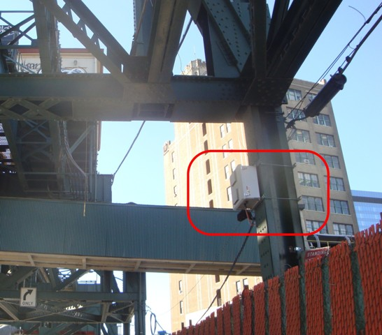
Industrial Embedded Monitoring – Remote Structural Health Monitoring using a cRIO

Industrial Embedded Monitoring – Remote Structural Health Monitoring
Using a cRIO to remotely assess structural health
By connecting these systems with a host PC, we can monitor continuous vibration activity and alarm conditions on a variety of structures despite inclement weather.
Challenge
Continuously monitoring the structural health of the Long Island Railroad (LIRR) Viaduct despite the relative inaccessibility of the structure.
Solution
Using CompactRIO, LabVIEW FPGA, and the LabVIEW Digital Filter Design Toolkit to measure the modal analysis of vibration data generated from ambient excitation, capture this data remotely, and analyze significant events.
Background
Engineers use structural vibrations to assess the conditions of many constructions and machines, including buildings, bridges, dams, towers, cranes, and mountings. Although we have had tools to monitor structural vibration for decades, these tools restrict data collection to short durations of high-fidelity waveforms or longer durations of summarized power in frequency band results. Many structures vibrate in meaningful ways only in the presence of ambient forces such as wind, vehicle activity, nearby construction, or random events such as earthquakes and tornados. Therefore, data collection needs to be active during these events.
Due to recent improvements in memory storage, processor speed, and wideband wireless communications technology, we can collect high-fidelity waveforms over long periods. We can also communicate to host PCs that aggregate structural vibration data across multiple collection locations, providing permanent data collection and superior analysis and reporting capabilities.
STRAAM Corporation, a leader in structural integrity assessment, and Viewpoint Systems, a Select National Instruments Alliance Partner, collaborated to develop a system that functions outdoors and in other less-accessible sites and maintains the capabilities of the available PC-based solution. Ultimately, we produced an enhanced version of STRAAM’s SKG CMS™ system to install on a Long Island railroad bridge.
System Requirements
The system needed to perform the following operations:
- Collect data from accelerometers and other environmental sensors
- Store weeks of data locally at full acquisition rates
- Analyze custom data in real time
- Publish summary statistics periodically to the host
- Upload waveforms to host on request
- Offer rugged, lightweight, cost-effective, reliable OEM deployment
- Contain flexible architecture to handle future capabilities
- Ensure secure user access control
System Design
We chose a system based on the NI CompactRIO platform and dynamic signal acquisition (DSA) C Series modules. The CompactRIO and associated C Series signal conditioning modules have an operating temperature range of -40 to 70 °C, well within typical environmental extremes for most installation locations. Additionally, the CompactRIO controller has no moving parts, increasing the mean time between failure and ensuring it can withstand physical mishandling during shipment and installation. For software, we decided to use the NI LabVIEW Real-Time Module and the LabVIEW FPGA Module. We used LabVIEW FPGA for basic signal acquisition as well as some custom antialiasing filtering to allow for sampling rates below the capabilities of the DSA module.
Figure 1 – Equipment mounted to LIRR Support Beam
Data Acquisition and Filtering
The DSA module acquired acceleration signals via special sensors, supplied by STRAAM, that output information about tilt and acceleration. Because large structures resonate at low frequencies, it is important that these sensors have extremely low noise, high dynamic range, and low frequency response to gather information about structures at less than 1 Hz. The low frequency range and long-term data storage need combine to create a maximum data collection rate frequency of 200 samples per second (S/s). The NI 9239 does not sample that slowly due to its delta-sigma converter technology, so we sampled at 2,000 S/s and used lowpass digital filtering on the field-programmable gate array (FPGA) to produce an antialiased signal at 200 S/s. Simple subsampling through decimation would violate the Nyquist criterion. Using the LabVIEW Digital Filter Design Toolkit, we produced a 28-tap infinite impulse response (IIR) filter with a 3 dB roll-off at 0.8 times the sample rate with a stopband attenuation greater than 90 dB. The Digital Filter Design Toolkit includes tools to automatically generate code to deploy the filter to the FPGA. We carefully selected fixed-point arithmetic to ensure proper operation without using excessive FPGA resources. The final filter was a 24-bit fixed-point solution with a 4-bit mantissa.
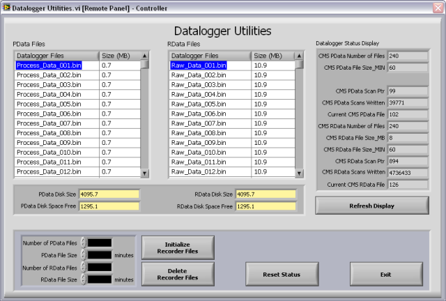
Figure 2: Remote Front Panel Displaying Acceleration Waveform Capture
Configuration, Signal Processing, and Alerts
STRAAM uses proprietary analysis routines, based on the structure’s resonant frequencies, to extract relevant information from the continuous stream of acceleration data. Because ambient energy excites the structures, we analyzed some initial data to locate these resonances. After this initial period, we configured the CompactRIO to perform the proprietary analyses based on the location of these resonances. We handled all activity in this initial setup remotely via wireless communications. We connect to CompactRIO over a wireless connection, then to a LabVIEW remote panel where we initially acquire and assign resonance bands.
The signal processing requires the spectral power and time-domain structure of the waveforms inside those resonant bands. The CompactRIO processor and FPGA module can calculate fast Fourier transform (FFT)-based power spectrums and perform time-domain filtering calculation so we can base calculations on the complicated algorithms provided by STRAAM. Furthermore, the large CompactRIO RAM can archive raw acceleration waveforms for later retrieval. The LabVIEW development environment greatly simplifies adjusting these calculations. We apply additional calculations to identify noteworthy events to alert the engineers when important conditions occur. These conditions may signify the presence of a meaningful ambient excitation or that considerable changes to the structure have occurred.
Host Communication
In order to successfully operate, this system needs to communicate effectively to the host PC. Because the system is deployed in almost-inaccessible and outdoor locations, all interactions with the system should occur remotely. Using cellular modems, the system connects via TCP/IP to upload important information, issue event alerts, and allow remote configuration. We designed the LabVIEW application to send periodic summary information via custom binary messages to the host with information about the condition of the structure and the CompactRIO system. The host then tallies this information along with all other SKG CMS™ systems deployed in the field. In addition to this summary information, the host can pull raw waveform data from the CompactRIO RAM. To avoid tampering and unauthorized access, we password protected all connections.
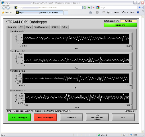
Figure 3 – Data File Configuration Screen
Summary
We have successfully installed several functional SKG CMS™ systems based on the CompactRIO platform. By connecting these systems with a host PC, we can monitor continuous vibration activity and alarm conditions on a variety of structures despite inclement weather. Our customers enjoy the benefits of modern Ethernet-driven, Web-based connectivity to verify the status of their structures and we enjoy the benefits of the rugged, reliable, low-cost, and reprogrammable CompactRIO system for data collection.
Manufacturing Test System for Electrical Components

Manufacturing Test System for Electrical Components
Replacing Obsolete Custom Electronics with cRIOs in High-Power Capacitor Testing
Modular Embedded cRIO-based Test Stands Shorten Development and Reduce Risk in Complex PC-based Test System
Client: A major manufacturer of electrical power generation and distribution equipment.
Problem Scope
This project involved retrofitting a test system used to verify operation of a high-power capacitor used in electrical power distribution. This system was originally built around 1990. Critical sections of the original test system relied on custom, wire-wrapped analog and digital circuitry to process, analyze, and isolate the high-voltage and high-current signals created by the capacitor. Analog filters, rectifiers, and comparators produced pass/fail status signals. A master PC, other measurement and control equipment, the analog circuits, and a six-position carousel were integrated to create the entire automated test and control system.
For each unit under test (UUT), test specifications are obtained from a Manufacturing Execution System (MES) and cached locally. The test stands at each carousel position are designed to run independently. This parallel capability allows greater throughput and reduced test time per capacitor unit. In addition, as different capacitor models move through the carousel stations, the test stand at each station must be aware of the particular model being tested at that station and adjust test parameters and conditions accordingly.
Test results for UUT are pushed back to the MES system for record retention and data mining. The existing MES interfaces were retained exactly for the retrofit.
Challenge
All capacitors require 100% testing prior to shipment, so the test system is critical for the facility operation. Two or even three shifts are common depending on production needs and the facility cannot afford any significant downtime. Thus, a challenge was to design and build a test system that worked and was very robust.
Another huge challenge was the lack of documentation on the existing system, requiring a sizable amount of reverse engineering to understand the test system operation before development on the new system could begin.
Furthermore, one of the most important challenges surrounded replacement of substantial amounts of original test equipment before the new test equipment could be installed. Thus, we absolutely had to minimize the time and risk in this upgrade changeover.
Technical Highlights
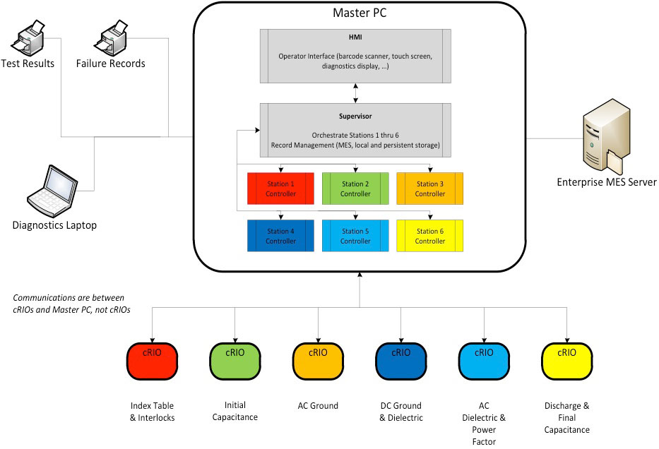
A schematic of the overall system architecture is shown in the figure. The major components of the system are:
- Master PC for supervisory control and test execution management
- NI cRIOs with FPGAs and Ethernet for test stands providing independent yet PC-supervised operation
- Station-specific FPGA code for replacing wire-wrap circuitry functionality
- Integration with existing MES, safety equipment, tooling, and measurement hardware
The architecture chosen was made very modular by the capabilities offered by the cRIO. The Master PC interfaced with station-specific measurement instrumentation as needed, such as GPIB controlled equipment, and coordinated control and outcomes from the cRIO-based test stands. This additional equipment is not shown in the figure.
Solution
The Master PC had three main functions
- Coordinating all the activities across the six cRIO-based test stands.
- Interfacing with the existing MES database and printers at the manufacturing facility.
- Providing the operator interface and, when needed, access to engineering screen on a diagnostic laptop.
The cRIO-based test stands were essential to the success of this test system. Each cRIO functioned as the equivalent of a high-speed standalone instrument.
The cRIOs at each carousel test position provided the following features:
- Digital I/O for machine feedback, safeties, and fault conditions
- State machines to coordinate with external commands and signals
- Perform numeric calculations to emulate the old analog circuitry
- Control loops for currents associated with voltages needed by different capacitors
- Communication support with the master PC
- Computation and detection of internal fault and UUT pass/fail conditions
We were able to duplicate the behavior of the wire-wrapped circuitry by converting the schematic diagrams of these circuits into FPGA code and then tweaking that code to mimicking the actual signals we measured with data acquisition equipment on the original test hardware.
The outputs of the circuitry were reconstructed on the FPGA with band-pass filtering, calibration compensation, point-to-point RMS, and phase & frequency functions. This functionality was implemented in fixed-point math and the 24-bit inputs on the A/D provided sufficient resolution and bandwidth for a faithful reproduction of the electronic circuitry. These embedded cRIOs provided a very effective solution to what otherwise might have required another set of costly and rigid custom circuits.
Finally, for optimizing the task of replacing the old equipment, we used a set of cRIOs, not shown in Figure 1, to provide Hardware-In-the-Loop (HIL) simulation of the manufacturing and measurement equipment. These cRIOs imitated the rest of the machine by providing inputs to and reacting to outputs from the embedded cRIO controllers, thus supporting comprehensive verification of the new test system before the tear-out of the existing hardware. Furthermore, these HIL cRIOs enabled fault injection for conditions that would have been difficult and possibly dangerous to create on the actual equipment.
We’ve helped teams at some of the world’s most innovative companies


Viewpoint Systems Industry Expertise

Manufacturing

Energy

Mil-Aero
Transportation