Condition Monitoring for Electric Power Generation

Monitoring generator and turbine components of power generation equipment
The CompactRIO-based system has allowed for continuous monitoring, rather than just a periodic review of turbine and generator performance. In addition, by combining the FPGA and the RT processor in a physically small device, the solution has been able to ensure very fast data acquisition, data reduction, and sophisticated analysis.
Client: A multi-national power generation equipment manufacturer
Background
Continuous monitoring of power generation equipment can have a great impact on maintaining a reliable flow of power to consumers as well as alerting the power generation equipment operator to potential equipment damage if timely repairs are not made.
This case study will focus on two measurement systems utilized by a multi-national power generation equipment manufacturer to monitor the generator and turbine components of their power generation equipment.
The manufacturer’s systems needed relatively high-speed waveform sampling, well-suited to the National Instruments CompactRIO platform. Viewpoint Systems provided technical assistance in the development of these systems.
Challenges
The difference in the types of analyses and data rates of the measurement systems required a flexible yet capable hardware platform. Each system needed to work on a generator outputting 50 Hz AC or 60 Hz AC.
Viewpoint’s Solution
The CompactRIO platform and LabVIEW proved to be an excellent solution for the electric power generation condition monitoring system’s data acquisition and analysis needs. The small size and robustness of CompactRIO allowed the system to be placed at a preferred location. In both the flux probe and the blade tip timing, the CompactRIO FPGA could acquire and pre-process the data. The CompactRIO successfully managed – and continues to manage – all analysis, data archiving, and communication with a host PC.
In the case of the tip timing, the data rates were high enough that the detection of the tip location for each signal needed to be performed in the FPGA so that the real-time (RT) layer received a much-reduced data rate of tip locations. The RT processor was able to perform higher level analyses on these timings. Occasionally, a snapshot of a raw tip timing waveform could be passed to the RT processor for archiving and presentation to an engineer. However, due to the data bandwidth and processor loading of the CompactRIO, such snapshots must be infrequent.
For both systems, a master PC managed the operator user interface, long-term data collating, reporting, and archiving of files and statistics. Each CompactRIO connected to this master PC via a TCP/IP connection.
Results
The CompactRIO-based system has allowed for continuous monitoring, rather than just a periodic review of turbine and generator performance. In addition, by combining the FPGA and the RT processor in a physically small device, the solution has been able to ensure very fast data acquisition, data reduction, and sophisticated analysis. By deploying CompactRIO devices, the multi-national power generation equipment manufacturer achieved a cost-effective method of monitoring the power generation facility equipment, ensuring detection of operational issues quickly and easily.
Technical Highlights
Both measurement systems described required sampling rates greater than 10 kHz, restricting the use of traditional PLC-based data acquisition devices and requiring a programmable automation controller (PAC). Each system measured the performance by connecting to special sensors and associated signal conditioning, provided by our customer, such that the data acquisition equipment only needed to support ±10 V signals. Furthermore, each of these systems needed to push data to a master PC for data trending, result archiving, and operator display.
Despite the significant differences in the measurement types, Viewpoint Systems was able to utilize a common set of data acquisition, processing, and connectivity tools, based on the NI CompactRIO platform and LabVIEW, to monitor the system.
More information about each measurement system follows.
Flux Probe
The flux probe system looks for shorts in the windings of the generator. Each time a winding passes under the flux probe, the probe output increases. When a winding is shorted, the field created by the winding is reduced and detected as a lower amplitude output by the flux probe. The position of a shorted winding inside the generator can be located by measuring a key-phasor signal that pulses once per revolution and converting the timing offset of this weakened signal into an angular position. Both flux and key-phasor signals are measured at about 50 kS/s.
Figure 1 shows an example signal output by a flux probe. The local peaks are indicative of winding current. Automated analysis of the amplitudes of the flux signals can be challenging due to changing waveform shape as a function of generator load and severity of shorts.
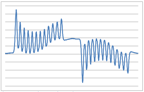
Figure 1 – Example flux signal over a single rotation
A good reference of the flux probe technique is described in the Iris Power Engineering article, “Continuous Automated Flux Monitoring for Turbine Generator Rotor Condition Assessment.”
Turbine Tip Timing
The turbine tip timing system looks for displacement of each turbine blade tip from nominal position. At slow rotational speeds, the spacing between each tip closely follows the uniform blade spacing. At higher speeds, vibrations and resonances can make the blade tips wobble slightly, causing small deviations in the timing of the tip passing by a sensor.
A special proximity sensor detects the tip of the turbine blade, and can be based on optical, eddy-current, microwave, and other techniques. Any positional deviations of a tip from nominal give indications about the mechanical forces on the blade as well as compliance of the blade to those forces as the blade ages. Specifically, each blade has natural resonances and compliance, both of which can change if the blade cracks.
A turbine typically contains several stages and each stage contains many blades. See Figure 2 below for an example. The number of tip sensors per stage is variable; if blade twist is measured, at least two sensors are oriented perpendicular to the rotation direction. Also, the acquisition rate from each sensor is fast. For example, consider a stage with 60 blades, the width of each blade occupying about 1/10 the space between adjacent blades, and a generator running at 3600 RPM (60 Hz). The tip sensor would detect a pulse every 1/3600 s, lasting for less than about 1/36000 s, as the blades passed by. Accurate location of the pulse peak or zero-crossing then requires sample rates over 100 kS/s. Because multiple sensors are typically used, tip timing measurement systems can easily generate 10s of MBs of data per second.
Figure 2 – Example generator turbine blades
A good reference for the tip timing technique is described in the article by ITWL Air Force Institute of Technology – Poland, “Application of Blade-Tip Sensors to Blade-Vibration Monitoring in Gas Turbines.”