
Manufacturing Test System for Electrical Components
Replacing Obsolete Custom Electronics with cRIOs in High-Power Capacitor Testing
Modular Embedded cRIO-based Test Stands Shorten Development and Reduce Risk in Complex PC-based Test System
Client: A major manufacturer of electrical power generation and distribution equipment.
Problem Scope
This project involved retrofitting a test system used to verify operation of a high-power capacitor used in electrical power distribution. This system was originally built around 1990. Critical sections of the original test system relied on custom, wire-wrapped analog and digital circuitry to process, analyze, and isolate the high-voltage and high-current signals created by the capacitor. Analog filters, rectifiers, and comparators produced pass/fail status signals. A master PC, other measurement and control equipment, the analog circuits, and a six-position carousel were integrated to create the entire automated test and control system.
For each unit under test (UUT), test specifications are obtained from a Manufacturing Execution System (MES) and cached locally. The test stands at each carousel position are designed to run independently. This parallel capability allows greater throughput and reduced test time per capacitor unit. In addition, as different capacitor models move through the carousel stations, the test stand at each station must be aware of the particular model being tested at that station and adjust test parameters and conditions accordingly.
Test results for UUT are pushed back to the MES system for record retention and data mining. The existing MES interfaces were retained exactly for the retrofit.
Challenge
All capacitors require 100% testing prior to shipment, so the test system is critical for the facility operation. Two or even three shifts are common depending on production needs and the facility cannot afford any significant downtime. Thus, a challenge was to design and build a test system that worked and was very robust.
Another huge challenge was the lack of documentation on the existing system, requiring a sizable amount of reverse engineering to understand the test system operation before development on the new system could begin.
Furthermore, one of the most important challenges surrounded replacement of substantial amounts of original test equipment before the new test equipment could be installed. Thus, we absolutely had to minimize the time and risk in this upgrade changeover.
Technical Highlights
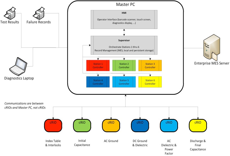
A schematic of the overall system architecture is shown in the figure. The major components of the system are:
- Master PC for supervisory control and test execution management
- NI cRIOs with FPGAs and Ethernet for test stands providing independent yet PC-supervised operation
- Station-specific FPGA code for replacing wire-wrap circuitry functionality
- Integration with existing MES, safety equipment, tooling, and measurement hardware
The architecture chosen was made very modular by the capabilities offered by the cRIO. The Master PC interfaced with station-specific measurement instrumentation as needed, such as GPIB controlled equipment, and coordinated control and outcomes from the cRIO-based test stands. This additional equipment is not shown in the figure.
Solution
The Master PC had three main functions
- Coordinating all the activities across the six cRIO-based test stands.
- Interfacing with the existing MES database and printers at the manufacturing facility.
- Providing the operator interface and, when needed, access to engineering screen on a diagnostic laptop.
The cRIO-based test stands were essential to the success of this test system. Each cRIO functioned as the equivalent of a high-speed standalone instrument.
The cRIOs at each carousel test position provided the following features:
- Digital I/O for machine feedback, safeties, and fault conditions
- State machines to coordinate with external commands and signals
- Perform numeric calculations to emulate the old analog circuitry
- Control loops for currents associated with voltages needed by different capacitors
- Communication support with the master PC
- Computation and detection of internal fault and UUT pass/fail conditions
We were able to duplicate the behavior of the wire-wrapped circuitry by converting the schematic diagrams of these circuits into FPGA code and then tweaking that code to mimicking the actual signals we measured with data acquisition equipment on the original test hardware.
The outputs of the circuitry were reconstructed on the FPGA with band-pass filtering, calibration compensation, point-to-point RMS, and phase & frequency functions. This functionality was implemented in fixed-point math and the 24-bit inputs on the A/D provided sufficient resolution and bandwidth for a faithful reproduction of the electronic circuitry. These embedded cRIOs provided a very effective solution to what otherwise might have required another set of costly and rigid custom circuits.
Finally, for optimizing the task of replacing the old equipment, we used a set of cRIOs, not shown in Figure 1, to provide Hardware-In-the-Loop (HIL) simulation of the manufacturing and measurement equipment. These cRIOs imitated the rest of the machine by providing inputs to and reacting to outputs from the embedded cRIO controllers, thus supporting comprehensive verification of the new test system before the tear-out of the existing hardware. Furthermore, these HIL cRIOs enabled fault injection for conditions that would have been difficult and possibly dangerous to create on the actual equipment.