
Attention LabVIEW Lovers: Did you know you can do Embedded Development with the NI SOM? – It Still Takes Effort of course
There are three main aspects to consider in order to successfully do embedded development with the NI SOM
You probably went to school for engineering. Maybe you took a LabVIEW class as a MechE or ChemE. Maybe you came up through the test world and now you work in a different capacity in a management role, or maybe you’re an entrepreneur with valuable domain expertise (maybe chemistry, maybe electro-mechanical machinery, maybe high power equipment for the smart grid, or maybe you know the rail industry). However you got here, you’re interested in developing a new embedded product for the industrial side of things (as opposed to consumer, which has its own unique set of challenges). You’ve got a great idea, but you aren’t sure how to get that idea to market. If you’re comfortable with, or have a love for, LabVIEW, there may be a path forward for you: the NI SOM.
There are three main aspects to consider in order to successfully do embedded development with the NI SOM:
- The NI SOM core hardware
- The development environment
- Additional Hardware
NI SOM Hardware
The NI System on Module hardware (the NI sbRIO-9651 SOM) consists of the bare necessities to act as the core processing element, including a processor, memory, some communication interface foundational elements, and an expansion connector. The processor is a Xilinx Zynq SoC, which is a pretty awesome little chip, incorporating both an FPGA and a dual-core ARM-based processor in a single silicon package. Check out the Zynq-7000 devices here.
For more details on the NI SOM, check out here as a starting point, and here for the device specs.
Development Environment
As a LabVIEW lover, this aspect is the main point of interest for you, as you’re comfortable with the graphical programming language (G) that the LabVIEW environment offers. In order to develop your embedded system, you’re going to be spending a lot of time in LabVIEW RT and LabVIEW FPGA (the percentage of each will depend on the specifics of your application of course, but to take advantage of the SoM you’ll need to use both).
However, there may be some low level hardware interfacing that requires the utilization of VHDL (or Verilog). For example, maybe you need access to some primitive within the FPGA (BlockRAM, IDELAY, BUFG, etc). Also, if you’ve got IP from a 3rd party that is in HDL, you’ll obviously be utilizing HDL. Check out this article on Getting Data In and Out of the NI-9651 System on Module (SoM)(especially the Socketed Component-Level Intellectual Property (CLIP) section) for more detail.
If you’re new to LabVIEW FPGA, here’s an intro article: LabVIEW FPGA – The Good, the Bad, and the Ugly. If you’re new to text-based HDLs, here’s another article for you: HDL FPGA Development – The Good, the Bad, and the Ugly.
If you don’t know LabVIEW RT or LabVIEW FPGA, you’ll need to either ramp up on these with some help from NI, or engage someone like a Viewpoint to help you (at least through your first project). The relative difficulty of these various programming methods along with the amount of code you might end up producing (in a very anecdotal / non-quantitative fashion), might look something like the following:
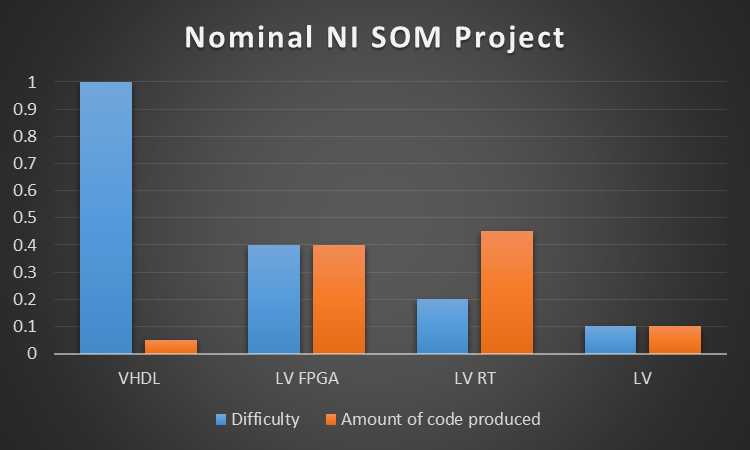
*- very unscientific chart
Note that even though you generally won’t develop straight LabVIEW code for your embedded system, you’ll likely develop some debug panels using LabVIEW.
It’s also worth noting that the real-time processor on the SOM is running a version of Linux. While you don’t need to be a Linux expert, it’s helpful to know some details about your operating system environment, so you can better design your software to work within the constraints of the embedded system. Linux is very powerful, however it does have its own mechanisms to process IO and tasks.
Additional Hardware Needs
If it’s not obvious yet, while the SOM gives you some very important core hardware to start with, you will need to design a custom circuit board to mount to the SOM and connect through the expansion connector. The sorts of circuits you will need will be things like:
- Power supply regulation (e.g., for the SOM components, other I/O components in your system). Some I/O may also require precision references to accurately sample the incoming data.
- Communication interface components (e.g., magnetics for Ethernet, transceiver for RS-232)
- Any I/O interfaces, analog or digital (e.g., signal conditioning, A/D conversion, GPS modules, LVDS translation, digital I/O buffers/drivers, etc.)
If you’ve got the appropriate custom circuit board design capabilities in house, then you have that option. If you don’t have in-house capabilities, or you don’t have the time to develop your own hardware, check out VERDI.
Next Steps
Hopefully this article has given you some things to chew on. Another way to talk about your embedded design is in terms of value layers, as in this diagram:
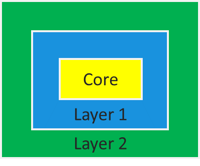
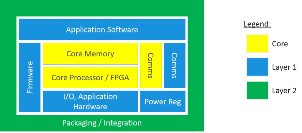
At the core you’ve got the NI SOM. Layer 1 includes things like the application software and custom electronics. Layer 2 would include the final packaging and integration into the final assembly. A more detailed visual is shown below.
If you’d like help with the NI SOM or anything in layer 1, or if you have questions about industrial embedded development in general, feel free to reach out to us. If you’d like to learn how to reduce development cost and risk with a SOM-based approach, go here. If you’d like more useful info on industrial embedded systems, check out our resources page.