
Product Testing Methods – for industrial hardware products
This paper discusses testing methods for industrial components/systems/subsystems, which are often complex or mission-critical, and either electromechanical or electronic in nature, with low to medium production volumes.
The focus is on hardware testing methodologies, although we’ll touch on software testing because a lot of hardware products contain a controller driven by some amount of software. We won’t be discussing certification-style testing (UL, CE, CSA, or any other of the many industry-specific certifications) or HALT/HASS testing in this paper, as those are their own specific sub-domains.
Poll – Test engineering leaders: What would help you most? Vote and see how your peers voted!
We’ll break this topic down into these sections:
- Testing methods for product validation vs manufacturing test
- Properties that can be measured for testing purposes
- Hardware testing methodologies for the mechanical aspects of your product
- Hardware testing methodologies for the electrical & electronic aspects of your product
- Testing methods for the software aspects of your product
- Realizing your product testing with an automated test system
Testing Methods for Product Validation versus Manufacturing Test
The main goal of product validation is to determine that the design of the product will meet its specification/requirements. It’s the earlier-stage ringing out of the design, sweeping and cycling through various stimulus (e.g., input voltage limits, load limits) & environmental dimensions (e.g., temperature, humidity, vibe) to help determine how the design will perform once it’s out in the world. These units under test (UUTs) are often exercised to the point of failure and are not intended to be sold.
On the other hand, the main goal of manufacturing test is to verify that the unit passes a subset of key specifications before it leaves the factory and heads to a customer. It’s often the final step before the unit is packed up and shipped out.
As such, these two categories of test often have different testing methods associated with them.
Product Validation Testing Methods
Product validation testing may have several different monikers attached to it, depending on the details of the goals of the test, but you’ll likely hear terms like HALT (Highly Accelerated Life Testing), environmental, endurance, durability, and reliability. The term regression testing may also come up. Regression testing is simply the subset of testing required to be performed to make sure the design still works after a design change was made.
Generally speaking, validation testing is going to involve one or more of these:
- Product stimulus sweeps –
In this case you’re trying to exercise the product’s inputs in order to see how the product performs. This could include things like:
- varying input power supply voltages
- hammering on a communication interface to determine any overflow/error conditions
- varying motor speed against various profiles
- pushing buttons with robotics at varying pressures and locations
- varying the load of an actuator to stress it mechanically
The product may be cycled through its paces many times (hundreds, thousands, millions) to test the durability or provide statistical significance for failure rates.
The product may be tested up to, or beyond its theoretical design limits.
- Environmental sweeps –
In this case you’re trying to stress the product’s environment in order to see how it performs. This could include things like:
- Running shock and/or vibe profiles
- Varying temperature
- Varying humidity
- Validating ingress protection from dust, water, or salt
- EMI (Electromagnetic Interference) chamber testing
Manufacturing Test Methods
When we talk about manufacturing test in this context, we’re generally referring to non-destructive final functional testing or end-of-line testing (we won’t get into HASS (Highly Accelerated Stress Screening) or board-level testing here).
With the main goal being a final check before the product leaves the factory, or the subassembly becomes part of a larger assembly, we generally want to perform things like:
- Verify that the behavior of the unit under test (UUT) is within a range of expected values
- Save the measurements and analyses captured during this assessment, for use by quality groups to assess designs and suppliers, and for use during possible rework and redesign of the UUT
- Alert the test operator of any issues or shutdown the procedure if imminent damage is suspected.
- Prepare a new or amend an existing record that will become part of the UUT’s history
This testing usually verifies a subset of what was checked out during the product validation phase. Further, the end of line testing equipment is often a subset of the equipment used during validation testing, but can be the same if the end of line test measures the same test parameters over a smaller range.
Properties that can be measured for testing purposes
Some testing is accomplished through digital interfaces, but a lot of testing is accomplished through measuring various properties of the UUT by attaching sensors to the device. Here are some of the properties that can be useful to measure for product testing purposes and a short list of common associated sensor types.
- Temperature – Thermocouple, RTD, infrared, thermistor
- Pressure – Capacitance, piezoelectric, piezoresistive
- Vibration – Accelerometer, prox, strain gauge
- Current – Current transformer/probe
- Voltage – Voltage transformer/probe
- Load – Load cells, piezoelectric, strain gauge
- Force – Strain gauge, accelerometer
- Flow – Volume flow, mass flow
- Light – Photodiode, photomultiplier, CCD, bolometer
- Acoustics – Ultrasonic, hydrophone, piezoelectric
- Location/orientation – GPS, accelerometer
- Distance, proximity – Laser, electro-optical sensor, camera, hall effect, infrared, capacitance
- Vision – Optical, infrared (see Light)
- Humidity/moisture – Capacitive, resistive
- RF Emissions – RF receiver
- Magnetic Field – Hall effect
The selection of each particular sensor is dependent on the exact type of test being performed as well as the characteristics of the component being tested.
Measured Signal Bandwidth
For example, testing for current draw by a motor could call for a current transformer (CT) with an RMS output, if you intend to know the quasi-steady state current draw of a motor that had been brought to a steady operating speed under a specified load. Or you may be interested in pull-in current when the electrical power is first applied to the motor, an important characteristic to know in order to properly size the power supply that will be supplying the current for the motor. Then, the test will need a fast response CT. And, if your motor is an AC motor, perhaps that sensor should be fast enough to measure the individual cycles of the AC driving the motor.
Similar considerations of responsiveness will apply to other sensors as well. Beware that some sensors require signal conditioning due to electrical isolation needs, to prevent ground loops, and may also be active (rather than passive), sensors such that excitation power needs to be supplied to them, often in the form of a DC current source. These additional electronics will affect the bandwidth of the signal acquired from the sensor.
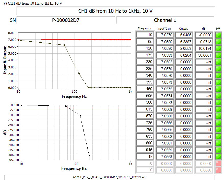
For example, a typical accelerometer for vibration measurement that requires IEPE excitation will have a high-pass filter (HPF) to block the output DC voltage offset caused by feeding the IEPE current to the sensor. That HPF will attenuate very low frequencies of motor vibrations. Typical sensors will have a cutoff frequency of 0.5 to 2.0 Hz. As another example of bandwidth effects, consider that electronic signal conditioning modules used for electrical isolation often apply a low-pass filter (LPF).
Another example occurs with encoders. Many encoders convert light intensity to a voltage level and note the angular motion by chopping a light source with a mask that alternates between passing and blocking the light source, creating an on/off output digital signal. Of course, the electronics that convert the light to voltage have a maximum bandwidth due to the responsiveness of the switch from off to on or on to off, and not necessarily with the same time response. That time response will limit the usefulness of the encoder when the motor speed is too high. A similar argument applies to the measurement equipment’s ability to respond to changing input voltage levels.
Inherent Sensor Bandwidth
The sensor itself can limit the bandwidth of your measurements. For example, if you want to test the temperature at the input electrical power connections during start-up, so you can watch the rate of heating, you should consider a temperature sensor that has a small mass compared to the connection material. A temperature sensor heats inversely proportionally to its thermal mass, and larger mass will act as a lower passband on the bandwidth of the sensor.
In general, be sure to choose your sensor responsiveness to match your needs.
Sensor Sensitivity and Accuracy
Sensors are designed to cover a finite range of the input physical parameter. For example, a flow sensor designed to measure the output of a kitchen water faucet will be overwhelmed by the flow from an fire engine pump. The first sensor covers a much smaller range than the second. You might wonder why a sensor with the large range shouldn’t be used for a small-range application. The reason is that the sensor sensitivity is related to its noise output. The electronics that convert the physical parameter to a voltage (or current) have inherent non-zero random noise. The amount of this noise generally increases with the range, so that as the range increases so does the noise level. A small change to the input of large range sensor would be overwhelmed by the output noise, making it difficult to detect that small input change: the sensor is not sensitive enough. More expensive sensors generally have lower noise and are thus more sensitive.
Accuracy accesses the correctness of the sensor output. Suppose you purchase a flow sensor of model M and that unit outputs Y volts when the flow is X cc/s. Will another unit of model M flow sensor also output Y when the flow is X? Generally, each unit of model M will output a slightly different Y value. The deviations across all units of model M is a measure of that model’s accuracy. More expensive sensors have better accuracy. Accuracy usually roughly scales with range, for the same reason that sensitivity decreases with range, i.e., the electronic components can add both systematic errors and random noise proportional to the range. Calibrating each individual sensor will improve that sensor’s accuracy by correcting for the systematic errors.
When choosing a sensor, make sure that you choose one with an appropriate range and accuracy.
Hardware Testing methodologies for Electromechanical Parts of your product
The breadth of electromechanical parts is enormous. This section will give a fairly detailed overview of the types of testing that are often applied to electromechanical components. The goal will be to describe the testing at a level above the physical attributes, such as temperature, pressure, force, and so on, but below the level of a final assembly inside of which that electromechanical component resides. This region is certainly bounded by murky lines but staying at this level will enable some tangible comments.
Electromechanical components are used widely in products that move, such as aircraft, compressors, engines, missiles, motors, rockets, valves, and so on. Testing electromechanical components involves a set of semi-standardized methods which often involve a common set of sensors and actuators.
Components
The following is a non-exhaustive list of the types of electromechanical components being considered:
- Electric motors
- Pumps and compressors
- Hydraulic Actuators, both position and force
- Valves, both proportional and on/off
Methods
At the core, testing these components comes down to using a set of common sensors that can be applied to these components.
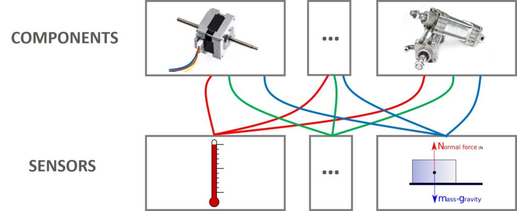
The graphic above shows the application of sensors to components. The match between sensors and component is not everything applied to everything, but the connections are almost like that. For example, a temperature sensor is often used to test some aspect of any electromechanical component while it is in use. However, an LVDT is often used for position measurements on a linear actuator but not (typically) a power drivetrain component. And similar technologies are used in sensors that are applied to different components. Following the LVDT example, testing a motor can involve a resolver, which uses similar technology as an LVDT, with primary and secondary transformer cores, but the interpretation of the signals is different between the two types of sensors.
Electric motor test methods
The behavior of an electric motor is often assessed by looking for the following features:
- Vibration of the motor housing and shaft
- Shaft radial runout and axial play
- Component temperature
- Excitation current and voltage
- Position and speed
- Torque
- Winding Conditions
For some specifics about these testing methods, see our article on motor testing methods.
Pumps and compressors
The behavior of a motor or engine driven pump compressor is often assessed by looking for the following features:
- Power consumption
- Vibration
- Component temperature
- Position and speed
- Shaft alignment
- Fluid properties (e.g., head and flow), both inlet and outlet
- Shaft Torque
- Cavitation
- Sound pressure
- Seal Leakage
For some specifics about these testing methods, see our article on pump and compressor testing methods.
Hydraulic Actuators, both position and force
The behavior of a hydraulic actuator is often assessed by looking for the following features:
- Null bias
- Stroke length
- Velocity
- Frequency or step response
- Solenoid drop-out and pull-in
- Hysteresis
- Proof pressure
- Relief valve operation
For some specifics about these testing methods, see our article on hydraulic actuator testing methods.
Valves, both proportional and on/off
The behavior of a valve is often assessed by looking for the following features:
- Opening and closing time
- Maximum flow rate
- Flow linearity, if proportional
- Hysteresis, if proportional
- Valve position sensor check (e.g., LVDT)
- Leakage rate
- Pressure drop versus flow rate
Hardware Testing methodologies for the electrical & electronic aspects of your product
Common methods for testing the various electrical or electronic components of your products include:
Memory testing
The goal here is to verify that the memory can be written to and read from without errors in writing or reading (or erasing). The type of memory (e.g. SRAM, SDRAM, EEPROM, Flash) and the criticality of how the memory is used together will influence the complexity of the testing. Some potential tests for consideration:
- Write/read walking 1s/0s
- Write/read counting patterns of data
- Write/read blocks of memory with pseudorandom data
- Write/read pseudorandom addresses with pseudorandom data
- Erase check
This testing may be performed at the board level as well.
Cable/interconnect testing
The goal with this testing is to verify proper connectivity from one cable/board to another cable/board. Errors may be caused by problems such as shorts, disconnects, crosstalk, or impedance issues. Some potential tests for consideration:
- Continuity check
- send/receive walking 1s/0s
- send/receive counting patterns of data
- send/receive pseudorandom data
Communication interface testing
The goal with this testing is to verify the ability to communicate to all applicable points, sometimes at a particular response rate or bandwidth if that’s a critical parameter. Depending on the type and criticality of the communication interface, the testing here may vary significantly. Some potential tests for consideration:
- Continuity check
- Point to point addressability check
- Pseudorandom data payload check
- Full rate bandwidth check
You’ll generally want to perform board level testing for verifying the basic functionality (e.g., power supply checks, processor checks, communication chip checks) of circuit boards, when board-level testpoints are more accessible.
Testing methods for the software aspects of your product
Testing the various software components of your product generally involves providing known stimulus (digital and/or analog signals) and data (i.e. messages) to the controller/processor and then verifying that the software produces an expected output response. The response can be another message or changes to the digital or analog outputs which the controller drives.
External lab equipment and specialized custom test software often provide the stimulus and the test software verifies the output of the UUT. For example, maybe the UUT is designed to set an output bit when a particular input channel has a sine wave of a particular frequency and magnitude present. The test system could command a signal generator to output various sine waves and make sure that the output bit on the UUT is only set when the sine wave being generated is within the specified range.
General testing software is extremely complex and generally. When a physical device is being tested, testing the software is generally focused on the I/O (signals and/or messages) that is sent to the device and the I/O response that results. This type of testing does not address all the possible paths through the software but instead exercises how the software responds to external influences. Often the test looks to see that the device is responding as required by the specifications in a requirements document, rather than looking to exercise the individual code modules. In other words, testing a device’s software often follows black box testing methods than whitebox testing methods. However, sometimes a complete whitebox verification is also performed.
Realizing your Product Testing with an Automated Test System
You’re generally going to need some combination of hardware and software in order to test your product. Often times you can get away with mostly off-the-shelf hardware (barring any custom cabling or test fixture needs), and usually some custom software.
- Cabling
- I/O modules and/or lab instrumentation
- Data acquisition
- Test execution software
- Test system user interface software
For more info on the various aspects of custom test equipment check out our LabVIEW Test Automation – Custom Test System Buyers Guide.
Next Steps
If you’ve got a product that needs testing and you need a custom test system developed, you can reach out to us here to start a conversation. if you’d like to see more about how we can help, see here.
If you’re deep into learning mode, here’s some other resources for you:
- Hardware Product Testing Strategy – for complex or mission-critical parts & systems
- Commissioning Custom Test Equipment – process, pre-commissioning checklist, and gotchas
- Test Automation Best Practices
- 5 Keys to Upgrading Obsolete Manufacturing Test Systems
- What is LabVIEW? – A developer’s perspective
- Hardware Test Automation Tools – for complex electromechanical product manufacturing
- Hardware Test Plan – for complex or mission-critical products