
Testing Methods for Hydraulic Actuators
Do you manufacture hydraulic actuators (or sub-systems with hydraulic actuators as components)? Do you want some ideas on how to test them?
If you’re interested in hardware product testing methods in general, you’ll want to check out our white paper: Product Testing Methods – for industrial hardware products.
Poll – Test engineering leaders: What would help you most? Vote and see how your peers voted!
The goal here is to describe the testing at a level above the physical attributes, such as position, pressure, and so on, but below the level of a final assembly inside of which the hydraulic actuator resides. This region is bounded by murky lines, but staying at this level enables tangible comments.
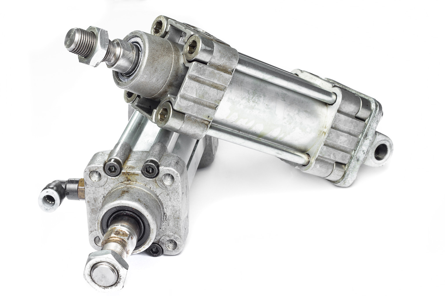
Hydraulic actuators are used widely in products that move, such as aircraft flight surfaces, earth-moving machines, motion simulators (e.g., for aircraft fight training and amusement park rides), rocket fins, and so on.
Features to Test
The behavior of a hydraulic actuator is often assessed by looking for the following features:
| Feature | Sensor |
|---|---|
| Null bias | Current shunt and Position |
| Stroke length | Position |
| Velocity | Position, flow meter |
| Frequency or step response | Position at various cyclic rates or step command |
| Solenoid drop-out and pull-in | Voltage, current, position |
| Hysteresis | Position for extend and retract cycle |
| Proof pressure | Pressure |
| Relief valve operation | Pressure, flow meter |
Note: When an actuator moves linearly, an LVDT or encoder is often used for position. For a rotational actuator, an RVDT is used rather than an LVDT. Also, preparation of the actuator is sometimes done by performing Dynamic Cycling on the part, whether in active mode or bypass mode. Such preparation is useful for purging air from the system and checking for external leakage prior to performing the test procedures.
Test Methods for various common tests performed on hydraulic actuators
Some of these tests require a resisting force (also called a load) to be applied so the device has something to “push” or “pull” against. Such forces are often supplied by another hydraulic ram or actuator.
Null bias
The test for null bias measures the current supplied to the control valve required to move the actuator to the “null position”. A reference position sensor verifies that the extension length of the actuator is mechanically correct and this position is checked against the sensor built into the actuator. The reference position sensor is usually either an LVDT or encoder. The unit position sensor is almost always, in our experience, an LVDT. Note that when the control current is step-changed to move the actuation to the null bias position, the actuator position will oscillate around the null position for a while, so the position check occurs after settling.
One subtlety in this test is caused by any null region designed into the control valve. The valve spool can move back and forth a small distance in this null region without any flow occurring. The consequence is that the null position is typically specified to be within tolerance when the spool is in this null region.
Stroke length
The actuator should move to the expected position when commanded to do so, and this test assures that the actuator does indeed perform as expected. This test is typically done in both extend and retract directions. The position sensor is usually an LVDT or encoder or both, especially if the accuracy of the LVDT built-into the product is being compared with the measurement from a calibrated external sensor.
Furthermore, the accuracy of internal LVDT(s) is checked at a set of length extensions to check for linearity of the sensor(s). As an important but indirect check during the stroke length test, the phasing of each LVDT output is checked to verify proper wiring of the two secondary windings relative to the primary winding excitation signal. If wiring has one of the secondary outputs reversed (plus to minus) relative to the other, the output signal phase will be different by 180 degrees.
Velocity
This test provides a step change in position to the actuator controller and measures the time response of the actuator movement to compute the speed at which the actuator extends or retracts. This test is usually performed under both loaded and unloaded conditions.
Two flavors of this test can be performed. One type applies the maximum allowed amount of current to the unit to check the maximum velocity that the unit can produce. The second type limits the current to the unit some know amount and verifies that the unit achieves this velocity.
For loaded conditions, multiple levels of loads will be used in the test. At each pair of load and commanded velocity configurations, the unit is verified that the velocity is as expected.
Frequency or step response
The step response looks for the rate of change in position when commanded to perform a step positional change. A similar test commands the actuator to cycle between two positions at a set of specific frequencies to compare the command to the response. The results are used to create a Bode plot.
Solenoid drop-out and pull-in
The solenoid that moves the spool in the hydraulic valve requires a minimum level of current to stay in position. The drop-out test slowly reduces the supply current until the solenoid switches state (e.g., open to closed) and notes this current level compared to the specification. The pull-in test does the opposite by slowly increasing the current until the solenoid changes state and notes this current compared to the specification.
Hysteresis
The amount of hysteresis exhibited by the actuator is based on the hydraulic valve, solenoid, and other components in the unit. The actual hysteresis is characterized in this test whereby the actuator is moved through its range of motion forward and backwards around the null bias position. Due to the potential for non-responsive behavior around the null position, a typical hysteresis curve has a double loop for forward and reverse directions around the null position. Each one of these loops is analyzed.
Proof pressure
This simple but important test applies a maximum amount of hydraulic fluid pressure to the actuator components to verify that they can withstand the pressure without leaking or, worse, bursting.
Relief valve operation
If the hydraulic components in the actuator are subject to extreme pressure, the relief valve opens to prevent damage. This test confirms that the relief valve responds properly to over-pressure by increasing the pressure until the valve opens and comparing that pressure against the specification.
Next Steps
If you need custom test equipment to test your hydraulic actuator or just have a question about automated test of hydraulic actuators, reach out here to start the discussion.
If you’re interested in other info on custom automated test systems, check out our Automated Test Systems Resources. You’ll find case studies, white papers, webinars, and articles.
Deep into learning mode? Check out these resources:
- Testing Methods for Pumps and Compressors
- Testing Methods for Electric Motors
- Product Testing Methods – for industrial hardware products
- Hardware Test Plan – for complex or mission-critical products
- Hardware Product Testing Strategy – for complex or mission-critical parts & systems
- Automated Hardware Testing – What Automated Hardware Testing is. Why do it. Types of Automated Hardware Testing. Commonly tested products. How to do it.