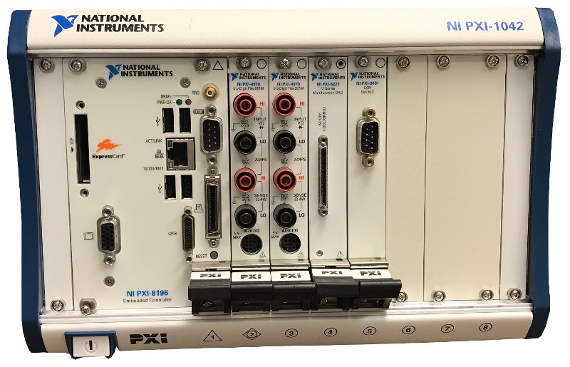
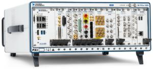
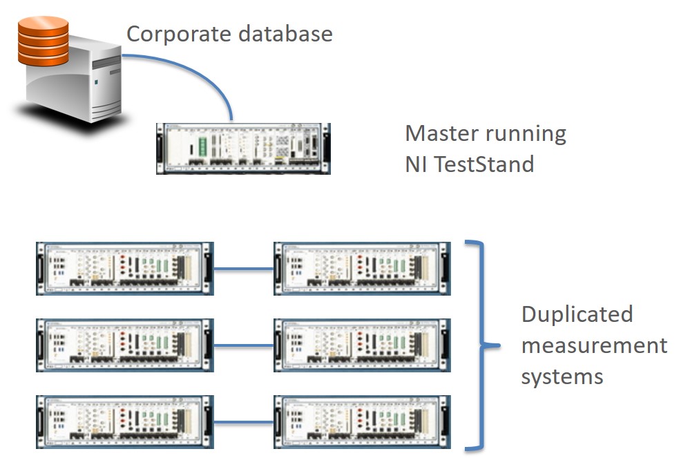
LabVIEW PXI Solutions – Need a PXI-based test system?
With over 1,500 PXI-based systems under our belt, we’ve utilized PXI for numerous manufacturing test and product validation applications. The broad range of off-the-shelf expansion cards and processing horsepower make PXI-based test systems a formidable choice for many automated test applications.

NI’s PXI platform is great for systems that require the wide range of test instruments that PXI supports, or that need the processing power of a PXI controller. PXI data acquisition hardware is capable of handling 1000s of digital and analog I/O. PXI test systems can process massive amounts of data with the latest CPUs or with some of the largest Xilinx FPGAs.
Viewpoint has used PXI for test applications revolving around:
We’ve utilized a lot of PXI modules, including:
| Need a PXI-based solution? Chat with a PXI Developer. |
|---|
Whether you’re looking for a turnkey solution or just want some help with a piece of your application, our PXI developers are here to help you.
Want more proof points? Check out these PXI case studies:
Transonic Wind Tunnel Test System Upgrade
Transonic Wind Tunnel Test System Upgrade
Improved Reliability, Reduced Stress, and New Tools People Want to Use.
Client – Calspan
(tunnel image courtesy of Calspan)

Challenge
Calspan operates a transonic wind tunnel capable of continuous Mach-speed testing a wide range of aircraft designs.
The overall test system was comprised of three subsystems that were all state of art at the time of design, over 20 years ago, but components were either obsolete or soon becoming so.
Calspan contacted us, and others in a competitive bid, to design, reuse, replace, and build a new test stand to maintain and even upgrade the test capabilities. At a high level, the requirements were to provide similar signal conditioning, hardware functionality, and software user experience.
Working together
Collaboration between our teams was key to success for this upgraded test system.
From the start, we all agreed that we’d have to do some reverse engineering to extract the details and nuances of the existing test system. This task was accomplished by reviewing existing items such as documentation and C++ code. As anyone who has done obsolescence upgrades knows, sometimes the source code is the best source for system requirements due to the wealth of details inherent in source code. Also, some aspects of system operation could not be easily documented, and Calspan personnel helped with defining the desired user interface and user experience.
The reverse engineering effort was enlightening and critical to assure that we all knew where we were headed.
Some highlights of design topics on which we collaborated:
The balance between full automation and manual operation was also discussed during initial collaboration. Calspan felt more comfortable with, and was familiar with, operating in a semi-manual mode, where walking through a test sequence was best handled semi-automatically with a set of operators at their stations. Nevertheless, we were able to suggest some improvements to the system useability and extensibility. For example:
Overall, we followed an iterative, Agile-like approach to design while using the technical details of the existing hardware and source code from the three subsystems to dictate the requirements necessary to reproduce, and even extend, the existing functionality.
Solution
The data acquisition part of the test system was implemented in two parts:
- a Precision Filters, Inc. (PFI) signal conditioning front end and,
- a National Instruments PXIe data acquisition chassis and modules. The PXIe chassis is connected to a server-class PC with MXI to handle all the acquired data and communication messaging between this test system and other special instruments and subsystems.
The signal conditioning was implemented with 128 channels of Precision Filters, Inc. 28124 transducer conditioner. This hardware is the only equipment on the market that met the needs of the client due to its capabilities for voltage and current excitation and a slew of gain and analog filtering options. PFI equipment is used extensively in wind tunnel and other critical measurement applications where performance, stability, and reliability are crucial, so the fit made a lot of sense. Also worth noting, although PFI offers an API to their chassis to enable automated or interfaced calibration, we chose to use their native calibration application because it just works and our interface would have been just a thin shell talking to their software.
The PXIe data acquisition is comprised of 128 channels of 24-bit, 200 kS/s digitizer analog input and additional 24-bit, 5 kS/s digitizer analog inputs. The PXI equipment is connected to a server-class PC via an MXI interface. The MXI interface offered the required bandwidth, and the server-class PC had plenty of processing power to manage the data flow from A/D to file storage while tending to the user displays. This arrangement is capable of simultaneous processing, alarming, visualization, and storage to disk at full rate.
Software was implemented almost entirely using Visual Studio C# and .NET 8.0. A small, but important, signal transformation portion was developed in LabVIEW Real Time on a Compact RIO.
User interface, test and sensor configuration, data acquisition, data processing, data storage, force balance calibration and alarming are all implemented in .NET.
Another overall goal was Calspan’s desire to maintain the application software. We tackled this goal in two ways:
- First, the original software spanned 4 code bases: 3 for the 3 subsystems mentioned above and 1 for calibration measurements. Not an ideal arrangement for software maintenance. When we rewrote in C#, the code base was refactored so that common software classes could be shared, such as data acquisition functionality.
- Second, it is very typical that Calspan’s customers have some unique measurement requirement such as specific sensor selection or additional measurement or control equipment. These requests are more easily accommodated by Calspan now, as compared to the previous system, because the refactoring and combining of the apps simplifies code edits.
Benefits
The main benefits of this obsolete test system upgrade were:
Also important to mention is the benefit of working with a collaborative team. The existing system, composed of the multiple subsystems, was complex with many subtleties. As with many older systems, the existing documentation was missing some important requirements – it’s just plain hard writing requirements. Without Calspan and Viewpoint having an open dialog and willingness to spend the time to understand options and make appropriate tradeoffs, the benefits of this upgrade project would not have been realized as cleanly. The collaboration was especially important in the design and acceptance testing phases of the project.
With this upgrade, Calspan has a reliable and flexible testing platform.
The previous hardware was degrading and, while not preventing tests from proceeding, channels were increasingly unusable as they failed. The replacement data acquisition hardware upgrades the previous test system with 128 high-speed channels, up from 96, and adds 32 low-speed channels. Previously, the test system acquired these high-speed channels at 100 kS/s per channel. Now the high-speed channels can be acquired at 200 kS/s per channel. All channels are now at 24-bit resolution up from 16-bit, vastly improving dynamic range. Finally, the fast- and low-speed channels can be combined into 160 channels of low-speed data with alarms (via real-time signal processing).
This new and modernized wind tunnel test system also brings faster test configuration. Calspan noted to us that two of the biggest improvements for a test setup configuration are having software-selectable filtering (i.e., not needing to change hardware modules) and having integrated multi-rate data acquisition (i.e., without having to patch in and set up separate acquisition hardware). Calspan estimates saving 2 to 4 hours per test setup.
Moving forward, Calspan will be able to satisfy their customer’s needs with this improved test system performance and the ability to reconfigure or expand functionality for future programs.
How we helped
System Overview

| SOFTWARE FUNCTIONS |
|---|
| Channel configuration |
| Alarming |
| Real-time graphs |
| Calibration for 6-axis and 1-axis sensors |
| Data storage |
| HARDWARE USED |
|---|
| Dual 19″ rack test stand |
| Precision Filters 28124 modules, 28000 chassis, and associated connectivity hardware |
| NI PXIe modules and chassis for high-speed AI |
| NI cDAQ and cRIO for AIO and DIO |
| Server-class PC |

Selecting replacement hardware for an obsolete test system
Selecting replacement hardware for an obsolete test system
A disaster hits – repair to meet schedule, and then upgrade after
Client – A major aerospace company

Challenge
Our client’s design validation test system was about 10 years old. They realized that the NI hardware in the test system was soon to be obsolete and they would have to upgrade it someday.
That day came sooner than expected when an issue in the test cell room caused excessive temperatures and smoke, overheating some PXI hardware and other components in the test rack. The test system had to be upgraded. (Everyone was OK – the issue was handled quickly.)
The timing of this event was especially unfortunate, as they were in the middle of some testing that needed to be completed to meet a schedule so that they didn’t hold up the design team.
So, the client made the decision to replace the existing PXI modules with the same type, rather than upgrading directly – that upgrade would have to come later. But, even after replacing the failed modules with the same part numbers, something wasn’t correct since the system didn’t work.
Working toward a solution together
Our client contacted us for help get them past this hurdle.
It turned out that the software for the original system was developed by a one-man system integrator with whom we occasionally collaborate. Our client asked that integrator to help, but he was unable to respond rapidly, so we worked with this integrator to pick his brain about possible causes, but no obvious solution was forthcoming.
We dug into the issue, which was a timing error, and discovered that one of the replacement boards needed a hardware driver update, even though the catalog part number was the same as the module being replaced.
This troubleshooting was best suited for someone with intimate knowledge of NI hardware – it took longer to figure out the issue than it did to fix it.
With that issue resolved, and after our client performed their tests, they asked us to start designing a test system to replace the soon-to-be obsolete hardware with new hardware.
Replacement with new hardware was not a one-to-one swap, making this design a perfect fit for our Hardware Selection Services consulting.
We took the details and requirements of the existing test system and figured out the replacement hardware. We needed to consider channel counts, acquisition rates, and costs. For example, the Sound and Vibration card in the original system had 8 channels but a replacement only had either 4 or 6 channels. Other tradeoffs were also made.
Our approach for this type of consultation:
- starts with recommendations to the client,
- followed by discussion about pros and cons,
- and ending (maybe after a few iterations) with a replacement system that meets the functionality of the original system. The client even added some additional functionality he’d been wanting for a while.
The cost of this consultation service was covered by purchasing of the hardware from Viewpoint, and, in this instance, that portion of our service offering worked to the client’s advantage because we worked with him to split the order into two parts to help him meet his budget and scheduling needs due to some long-lead items. Specifically, we worked with NI to swap a controller running the latest version of Windows with one that ran the previous version so that we could hit shipping dates 5 weeks earlier than otherwise. Our experience with the NI buying process was critical to rectifying this situation; a typical NI customer wouldn’t have thought to check for this solution.
After the arrival of the new system, we were contracted by the client to rework the software to use the new hardware. Updated drivers were needed, of course, but since the original integrator had given the client the application LabVIEW source code, we could decipher how it operated and were able to determine how to incorporate the new and different channel configurations per card plus supporting the functionality that the additional cards offered. Once the configuration of this new hardware setup was completed, we tested that the application was once again working as expected.
Benefits
Working with an integrator that offers both consulting for selecting new NI hardware coupled with turnkey test system design and build capabilities enabled our client to move from a broken system to a new one in stages.
This approach enabled them to complete their scheduled tests as quickly as possible while giving them a path to the future based on the new system that we helped them build and deploy.
How we helped
For this project, we mostly helped with the selection and replacement of NI hardware with a little side help from some system integration services to bring the test system application software to full functionality.
System Overview
| SOFTWARE FUNCTIONS |
|---|
| LabVIEW app for data acquisition, display, and storage |
| Configuration of channels through MAX for connection to the LabVIEW app via DAQmx |
| Test sequencing definition for system control via output channels |
| HARDWARE USED – (for replacement system) |
|---|
| NI PXIe controller and chassis |
| NI Sound and Vibration cards |
| NI Timing and sync card |
| NI Thermocouple card |
| NI General analog I/O |
Replacing Wire-wrap Boards with Software, FPGAs, and Custom Signal Conditioning
Replacing Wire-wrap Boards with Software, FPGAs, and Custom Signal Conditioning
Electronic components of fielded systems were aging out
Reverse engineering effort converted wire wrap boards to FPGA-based I/O
Client – Amentum – A supplier for Military Range System Support
Challenge
Amentum (www.amentum.com) supports a decades-old system deployed in the early 1980s. While the mechanical subsystems were still functioning, the wire-wrapped discrete logic and analog circuitry was having intermittent problems.
Systems designed and built decades ago can sometimes have wonderful documentation packets. Nevertheless, we’ve been burned too often when the docs don’t incorporate the latest redlines, last-minute changes, or other updates.
The replacement system needed to be a form-fit-function replacement to land in the same mounting locations as the original equipment with the same behavior and connections. Below is an image of the existing wire-wrap boards and their enclosure. We had to fit the new equipment in this same spot.
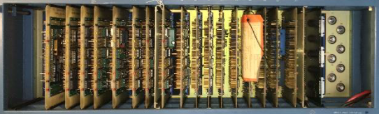
Figure 1 – Original wire-wrap boards
Finally, Amentum wanted to work with Viewpoint in a joint development approach. While our joint capabilities looked complementary, we didn’t know at the start how well we would mesh with our technical expertise and work culture – it turns out we worked extremely well together as a team and neither one alone could have easily delivered the solution.
Solution
Since the team treated the existing documentation package with suspicion, we adopted a “trust but verify” approach. We would use the documents to give overall direction, but we would need details from the signals to verify operation.
Leveraging Amentum’s experience with the fielded systems, the team decided early on to record actual signals to understand the real I/O behavior. We used the system’s “test verification” unit to run the system through some check out procedures normally run prior to system usage. This verification unit enabled us to use a logic analyzer for the I/O to and from the discrete logic digital signals and an oscilloscope and DMM for the analog signals. The available schematics were reviewed to assure that the signals made sense.
With a trustable understanding of system operation, Amentum created a requirements document. We jointly worked on the design of the new system. There were both an “inside” system (in a control shelter) and an “outside” system (in the unit’s pedestal).
Some overall tasks were:
- Viewpoint recommended an architecture for the inside application running on PXIe LabVIEW RT and FPGA layers.
- Amentum created the system control software on a Linux PC.
- Viewpoint developed the more intricate parts of the inside application and mentored Amentum on other parts they developed. This work recreated the existing discrete logic and analog I/O using PXIe NI FPGA boards.
- Viewpoint designed custom interposer boards to connect harnesses to the NI PXIe equipment, including a test point and backplane boards.
- Amentum designed and developed the cRIO-based outside system application and Viewpoint created a set of custom interposer boards to connect harnesses to the cSeries modules.
Critical to this project was our hardware selection services. By combining our engineering skills for the reverse engineering of the legacy electronics with our knowledge of the NI hardware, we narrowed the hardware choices to a few NI FPGA boards.
These PXIe FPGA boards and cRIO FPGA-backed modules handled the required 60 MHz clock-derived signals with correct phases, polarity, analog inputs, and so on. Furthermore, the wire-wrap boards were register-based so the PXIe had to decode “bus signals” sent over a Thunderbolt bus to emulate the programming and readouts from the various wire-wrap boards.
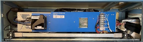
Figure 2 – PXIe replacement to wire-wrap boards
Amentum wanted to be able to support the LabVIEW FPGA VIs used to replace the functionality of the discrete logic. So, Viewpoint acted as mentor and code reviewer with Amentum to ramp them up on using LabVIEW FPGA effectively. Neither one of us alone would have been successful coding the applications in the allotted time. Joint knowledge and experience from both Viewpoint and Amentum were required.
Signal conditioning and harnesses needed to be reworked or replaced as well, of course, since the landing points for the wires were different in the new system. Viewpoint suggested a technique, which we’ve used frequently in past obsolescence upgrade projects, to create PCB boards that accepted existing connectors.
For the cRIO, these interposer “connection” PCBs plugged directly into the cRIO cSeries module. For the PXIe, these interposer PCBs accepted the field wiring connectors and converted them to COTS cables that connected to the PXIe modules. These interposer PCBs could have signal conditioning incorporated as needed. This approach significantly reduced the need for custom harnesses. All told, about 200 signals were passed between the PXIe and various other subsystems, and about 100 for the cRIO. This approach saved significant wiring labor and cost.
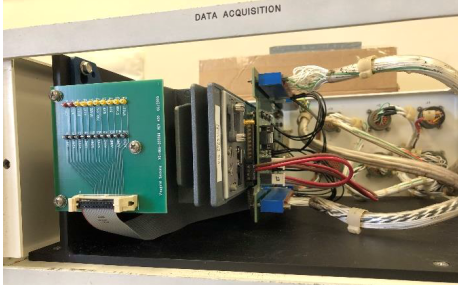
Figure 3 – cRIO with interposer boards between cSeries and field harnesses
The work to design and build the signal conditioning custom electronics was split between Viewpoint and Amentum. Viewpoint did more design than build and handed over the schematics and Gerber files to Amentum so they could manage the builds while also being able to make modifications to the boards as needed.
Benefits
Amentum wanted an engineering firm that was willing to work along side them as a partner. Joint discussions about architecture and design led to a collaborative development effort where Amentum benefited from Viewpoint’s extensive expertise and guidance on LabVIEW architectural implementation and FPGA coding style.
The main outcomes were:
- As a partner of the team, Viewpoint acted as staff augmentation by providing experienced engineers with technical capabilities that Amentum initially lacked.
- This team approach delivered a stronger product to the end-customer more quickly than either of us could do alone.
- The combination of Viewpoint’s and Amentum’s experience reduced the amount of reverse engineering needed due to the lack of firm requirements.
- Reduction of electronics obsolescence by using software-centric FPGA-based functionality. Recompiled LabVIEW FPGA could target future boards models.
- Increased software-based functionality simplifies future updates and modifications.
- Decrease in number of parts leading to simpler maintenance.
- Lower wattage consumed eliminated need for an anticipated HVAC upgrade.
- Cybersecurity concerns were reduced by using Linux-based systems and FPGA coding.
System Overview
Using software to emulate the old hardware was a critical success factor. Since the requirements were not 100% solid at the start of the project, some field-testing was required for final verification and validation. The flexibility of the software approach eased modifications and tweaks as development progressed. A hardware-only solution would have necessitated difficult and costly changes. For example, some of the changes occurred very near the final deployment after the system was finally connected to an actual unit in the field.
| SOFTWARE FUNCTIONS |
|---|
| Emulate original discrete logic functions via FPGAs |
| Emulate original analog signal I/O |
| Overall system control via Linux PC |
| Maintain the same user experience as existed before |
| Modern application architecture for simpler maintenance |
| HARDWARE USED |
|---|
| NI cRIO chassis with various cSeries modules |
| NI PXIe chassis with FPGA modules to handle all the analog and digital I/O via a combination of multifunction and digital-only cards |
| Custom PCBs for signal conditioning and connectivity |

Enhanced Portable Data Acquisition and Data Storage System
Enhanced Portable Data Acquisition and Data Storage System
Using a Real-Time Operating System (RTOS) provides a high level of synchronization and determinism for acquired data.

Client
Tier 1 Automotive Design and Manufacturing Supplier
Challenge
Our client had an existing data acquisition system, used for mechanical product validation testing, that had undergone many updates and patches for over 15 years. These updates and patches, performed by multiple developers, had rendered the software portion of the system somewhat unstable. Furthermore, the system hardware was based on NI SCXI, which was becoming obsolete. These issues prompted our client to migrate to an entirely new system.
New requirements for this upgrade included utilizing a PXI controller running NI Linux Real-Time, a RTOS, executing a LabVIEW RT application. Selection of the replacement NI hardware required knowledgeable engineering to assure compatibility between the selected NI hardware and the legacy SCXI equipment. Part of that compatibility assessment included an understanding of the software application so we could know for certain how the SCXI equipment was used. A blind selection based entirely on hardware specs would have missed nuance, such as the need for synchronized acquisition.
The data acquisition software had to support a variable mix of signal conditioning modules in the PXI chassis. In addition, the data acquired from these signal conditioning modules needed to be synchronized within microseconds.
Solution
Viewpoint leveraged another application, developed for the client a few years prior, to harmonize the user interface and to reduce development effort. Most of the development time focused on support and configuration of the multiple module types and ensuring that the data synchronization functioned as required. The result was an ultra-flexible, portable, high-speed data acquisition software/hardware combination that can be used to acquire time-sensitive, synchronized data across multiple modules in a PXI chassis running a real-time operating system.
Benefits
The upgraded system offers the following features:
- Highly configurable real-time data acquisition hardware/software solution based on LabVIEW RT and PXI hardware. Our client works closely with OEMs to assure compatibility and durability with their products, often going to the OEM’s test cells to collect performance data. The configurability in modules and channels affords the fastest possible setup at the OEM’s site which minimizes time and cost in the test cell.
- Configuration files stored in a SQL database format. Saving channel and module setups in SQL allows the test engineer to locate previous hardware and data acquisition configurations. The usual alternative is a bulk save of an entire system setup rather than using a more granular, and hence, more flexible approach afforded by using the database.
- Immediate test feedback through graphs and analog indicators, used to assure data quality before leaving the test cell.
- Data playback features after the data has been acquired, used for in-depth review of data after leaving the test cell.
- Data acquisition on the RTOS provides assurance that the acquisition will not be interrupted by network or other OS activities, which was occasionally an issue with the prior Windows-based application.
- Synchronization between signal conditioning modules ensures time-critical data taken on separate modules can be compared and analyzed.
System Overview
The system consisted of custom LabVIEW RT software intended to run on an engineer’s laptop and the PXI real-time controller and a PXI chassis populated with a flexible assortment of NI signal conditioning modules (provided by the client).
The software used an object-oriented Actor-based architecture, which facilitates adding new signal conditioning modules and flexible communications between the host PC and the real-time controller.
| SOFTWARE FUNCTIONS |
|---|
| DAQ Task Configuration |
| Event-Based DAQ Trigger |
| Data Synchronization |
| Real-Time Data Visualization |
| Data File Playback Utility |
| Datalogging to TDMS File |
| HARDWARE USED |
|---|
| PXIe Chassis (4,9 or 18-Slot) |
| PXI Real-Time Controller |
| PXI Multifunction I/O Module |
| PXI Digital I/O Module |
| PXI Counter/Timer Module |
| PXI Thermocouple Module |
| PXI DSA Module |
| PXI LVDT Module |
| PXI High-Speed Bridge Module |
| PXI Voltage Input Module |

Industrial Monitoring for a Harsh Environment
Industrial Monitoring for a Harsh Environment
Developing an industrial monitoring system for ultrasound-based sensing in a harsh environment
Client – Energy Research Lab
Challenge
Our client was experiencing problems making temperature measurements in a hostile, irradiated environment. Traditional temperature sensors don’t last long in this environment, so our client was developing a sensor designed for these conditions.
Special equipment is required to drive this sensor. It’s an active sensor requiring an ultrasound pulser/receiver (P/R) and high-speed digitizer to make it function.
The prior attempt the client made at using an original set of special equipment was having reliability and connectivity issues. This reduced reliability was of critical concern due to the requirement for the sensor to operate for years without downtime.
In addition, the existing application was incapable of displaying live data and lacked a user-friendly interface. On top of that, data analysis had to be done after the application was run, causing delays.
Our client needed reliable and robust hardware to drive the sensors and an application that would eliminate the challenges associated with the existing system.
Solution
Viewpoint accomplished the following:
- Evaluated two different ultrasonic P/R sensor driver hardware solutions to select a solution that would provide the connectivity robustness, configurability, and correct sensor driver characteristics required for the given sensors.
- Decoupled the digitizer embedded in the original P/R by adding a PXI digitizer with better capability.
- Provided backward compatibility with previous measurement hardware to aid in performance comparisons with the new hardware.
- Developed a LabVIEW-based application that corrected all the issues with the existing application including real-time data analysis, real-time data visibility and a modern user interface. The new application also provided sensor performance traceability using the sensor’s serial number.
We selected the NI hardware and non-NI equipment to assure compatibility.
Benefits
The enhanced measurement system offers the following benefits:
- Reliable sensor subsystem to ensure uninterrupted data acquisition.
- Measurement hardware configurability for sample rate, collection duration, and pulsing repetition rate.
- Application configurability for automating the analysis, historical archiving, and results reporting.
- Real-time data analysis.
- Sensor traceability through serial number and data files.
- Engineering mode to take control of the entire measurement system.
- Improved data logging to include raw and analyzed data.
- Improved application user experience via robust data collection and configurability.
System Overview
The deployed temperature monitoring system consisted of the following components:
- COTS pulser/receiver hardware for driving the sensors.
- COTS high-speed DAQ for retrieving ultrasound signals.
- A LabVIEW-based software application to provide real time data monitoring, error/alarm notification, data analysis, data logging, part traceability and backward compatibility with the older sensor driver hardware.
| SOFTWARE FUNCTIONS |
|---|
| Acquire Data from Sensor Driver Device |
| Data Analysis |
| Write Raw Data to File |
| Write Analyzed Data to File |
| Configuration Utility |
| HARDWARE UTILIZED |
|---|
| Sensor Pulser/Receiver Driver |
| NI PXIe Expansion Chassis |
| NI PXI Oscilloscope Module |
| NI PXI Thunderbolt 3 Module |
| INTERFACES / PROTOCOLS |
|---|
| RS-232 |
| Thunderbolt 3 |
High-Speed Digital Subsystem Emulator
High-Speed Digital Subsystem Emulator
Client: A large company involved in C4ISR
At maximum throughput, the AEDIS systems needed to consume and produce more than about 800 MB/s/slot.
Background
A large company involved in C4ISR was developing a system for a new high-speed digital sensor device. Viewpoint was contracted to build a test system used in design validation and ultimately endurance testing of the sensor. Since the sensor was a component of a larger system which was being developed at the same time, another test system was created to simulate the sensor by feeding signals into the system. This ability to use HIL testing for both the sensor and the downstream sensor electronics enabled parallel development, thus saving time and reducing schedule.
Challenge
Both the amount of data and the frequencies of the various digital signals were nearly at the limit of hardware capabilities. At maximum throughput, the systems needed to consume during record and produce during playback about 800 MB/s/slot. The FPGA clock on the FlexRIO had to run up to 300 MHz. The skew between triggers for data transmission needed to be less than 5 ns even between multiple FlexRIO cards even when the parallel data paths have inherent skews associated with the sensor. Finally, the systems needed to handle clocks that might be out-of-phase.
Achieving these requirements required significant engineering design in the face of multiple possible roadblocks, any one of which could have eliminated a successful outcome.
Furthermore, as usual, the development timeline was tight. In this case, it was a very tight 3 months. Basing the solution on our AEDIS platform was critical to meeting this challenge.
Viewpoint’s Solution
To meet the timeline, we had to work in parallel across several fronts:
- LabVIEW-based application development for both record and playback
- LabVIEW FPGA development for marshalling data between the controller and DRAM
- Custom FAM circuit board design and build
- FlexRIO FPGA CLIP nodes and code for low-level data handling
Technical Highlights
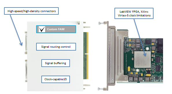
This sensor had several parallel data paths of clock and data lines with clock speeds up to 300 MHz on each path requiring exacting design and build of a custom FlexRIO Adapter Module (FAM) and unique custom CLIP nodes for extending the FlexRIO FPGA capabilities. The FAM also had a special connector for interfacing to the customer’s hardware.
Additional NI hardware and software completed the system components.
Results
The choice to base the AEDIS emulators on NI hardware and software was critical to completing this project. The open architecture in both hardware (custom FAM) and software (CLIP Nodes) enabled us to include some very creative extensions to the base toolset without which the project would not have succeeded in the allotted pressured schedule and on a predetermined budget. We were able to stretch the capabilities of the hardware and software very close to their maximum specifications by combining COTS and custom much more cost effectively than a purely custom design. Further, with HIL tests, both the sensor and the sensor electronics could be developed in parallel, leading to a significant schedule buyback for our client.
LabVIEW Layers
The host application, written in LabVIEW, managed the configuration of the data acquisition and the control of the LabVIEW RT-based FlexRIO systems. The configuration primarily dealt with the number of sensor channels in use, skew settings between digital lines, and other parameters that dealt with the organization of the data passed between the sensor and the FlexRIO.
Two FlexRIO applications were written, one for record and one for playback. Each FlexRIO application was written in LabVIEW, and managed the configuration of the FlexRIO cards and the movement of data between the FlexRIO cards and the RAID drives. Note that Windows supported for the RAID driver. Between 10 and 32 DMA channels were used for streaming, depending on the number of sensor channels being used.
And, each FlexRIO application had an FPGA layer, written in LabVIEW FPGA enhanced with custom CLIP nodes. For the record application, we developed a custom DRAM FIFO on the FPGA to assist with the latencies on the PXIe bus. For the playback application, we were able to stream directly from DRAM.
FlexRIO Considerations
The FlexRIO and stock FAMs from NI were initially considered as candidates for this project. Clearly, working with commercial-off-the-shelf (COTS) components would be most effective. Three options were available at the project start which could accommodate the required clock frequencies, but none offered both the required channel counts and skew/routing limitations. Hence, we had to design a custom FAM. This decision, made before the start of the project, turned out to be wise in hindsight because the parallel development path resulted in some shifts of sensor requirements which could be accommodated with the custom FAM but might have led to a dead-end with a COTS FAM.
FlexRIO CLIP
In LabVIEW FPGA, a CLIP Node is a method to import custom FPGA IP (i.e., code) into a LabVIEW FPGA application. CLIP stands for Component-Level Intellectual Property. We needed to use special Socketed CLIP Nodes (i.e., VHDL that can access FPGA pins) for this project because we could expose additional features of the Xilinx Virtex-5 not exposed in LabVIEW FPGA by accessing Xilinx primitives. Some specific features were:
- Faster FPGA clocking
- Additional clocking options
- Individual clock and skew control
- Custom PLL de-jitter nodes
Essentially, the FPGA design had a majority of FPGA code developed in LabVIEW FPGA and we used CLIP Nodes for interfacing the signals between the FlexRIO and the FAM.
FlexRIO Adapter Module
As mentioned earlier, we had to create a custom FAM because of the need to route high speed signals from customer-specific high density connectors while synchronizing signals across multiple data channels and FPGA modules to within one (300 MHz) clock cycle.
At these high-speeds, the FAM needed careful buffering and impedance matching both on the signals as well internal components on the FAM PCB. At the start of the design, we utilized Mentor Graphics HyperLynx High Speed DDR signaling Simulation software to minimize signal reflections prior to building actual hardware. This step saved countless hours in spinning physical hardware designs.
We designed the FAM to allow channel routing and access to additional clock and trigger pins on the Xilinx chip and PXIe backplane.
NI FlexRIO-based Custom Test Equipment for High Speed Digitizer sensor

NI FlexRIO-based Custom Test Stand for High-Speed Digitizer sensor
The initial interface/test system to the DUT was up and running and getting real data from the DUT in ~2 weeks, allowing the customer to maintain a tight development schedule.
Client – A Large Manufacturer
Challenge
Our client was developing an image sensor component and needed to validate the part for a new product line. They wanted to use as much COTs hardware as possible to start testing as soon as possible.
Solution
The custom product validation test equipment utilizes the NI PXI with FlexRIO off-the-shelf hardware combined with custom LabVIEW-based software.
Benefits
- The initial interface/test system to the DUT was up and running and getting real data from the DUT in ~2 weeks, allowing the customer to maintain a tight development schedule.
- Packet Decode completed at FPGA Level allowed error handling and only pertinent data being saved as needed.
- Data Manipulation done at FPGA level for unbundling data into correct disk readable format in real-time.
- All Data captured with TDMS Files to disk enables a higher level of analysis of the data offline.
System Overview
The new PXI-based automated test stand utilizes NI’s FlexRIO with NI stock LVDS FAM.
- Custom VHDL was created to handle the required adjustable delay lines in the data I/O lines and interface to the I/O on the FAM Connector.
- The VHDL interfaced to LabVIEW FPGA which was utilized to stream the data to disk.
- Data is stored onto disk during a test and only the payload data from decoding the protocol is saved.
- The data coming from the UUT is de-packetized and ordered for manipulation downstream.
| SOFTWARE FUNCTIONS |
|---|
| Custom FAM VHDL and LabVIEW FPGA interface Development |
| Custom LVDS Adjustable Delay lines per LVDS Data stream |
| LVDS Buffering |
| Generate multiplied Clock from external clock input to latch in data |
| Source the multiplied clock to Internal LabVIEW FPGA Clock |
| FIFOs for clock domain crossing and DMA |
| High-speed data streaming to Disk |
| LabVIEW RT for example interface to FPGA |
| GUI |
| HARDWARE USED |
|---|
| 19″ rack test stand |
| NI FlexRIO |
| NI FlexRIO FAM – LVDS |
| NI LVDS to flying lead cable |
| NI PXI chassis and controller |
NI FlexRIO enables Device Evaluation & Characterization for high-data-rate sub-system
NI FlexRIO enables Device Evaluation & Characterization for high-data-rate sub-system
100s of man-hours saved in capturing the data.
Client – Automotive Manufacturer
Challenge
New product development drove the need for validation of a new sub-system (a RADAR sensor ) for use in a next-gen system in an automobile. They needed a way to evaluate and characterize the performance of the component under various conditions that were not defined in the UUTs specs. They wanted to use as much COTS hardware as possible for this first run testing because of the expense of a custom test solution and the timeline.
Solution
The NI FlexRIO-based product validation system utilizes COTS hardware, along with some Viewpoint-developed custom software to allow for evaluation and characterization of the UUT.
Benefits
- The utilization of COTs (vs a custom-built FPGA board) test hardware.
- 100s of man-hours saved in capturing the data.
- Allowed customer to manipulate captured data within the LabVIEW environment for more efficient testing, making changes on the fly.
- Error Checking done at the FPGA Level allows for guaranteed valid transfers
- Packet Decode completed at FPGA Level allows for real-time de-packetization for use in storing only payload data.
- All Data captured with TDMS Files for use in over layering different scenarios.
- Scalable to add additional serial data channels allowing for more than one sensor to be captured with a single FlexRIO card.
System Overview
NI’s FlexRIO with NI’s LVDS FAM was used. The NI flying lead cable was utilized initially to connect to the UUT. On the software side custom VHDL was created to handle the 8b/10b serial stream data and clock recovery. The VHDL interfaced to LabVIEW FPGA which was utilized to stream the data to disk on the PXI-based system.
| SOFTWARE FUNCTIONS |
|---|
| Custom FAM VHDL and LabVIEW FPGA interface Development |
| Aurora 8b/10b de-serialization and clock recovery |
| LVDS Buffering |
| Clock to Internal LabVIEW FPGA Clock |
| FIFOs for clock domain crossing and DMA |
| High Speed data streaming to Disk |
| LabVIEW RT for example Interface to FPGA |
| GUI |
| HARDWARE USED |
|---|
| NI FlexRIO |
| NI FlexRIO FAM – LVDS |
| NI LVDS to Flying lead cable |
| NI PXI Chassis and Controller |
| INTERFACES / PROTOCOLS |
|---|
| Aurora 8b/10b |
| TCP/IP |
Custom Test System Using NI PXI for Electrical Test
Custom Test System Using NI PXI for Electrical Test
Updating an obsolete tester that maintains functionality
Client – Medical Device Manufacturer
Challenge
Our client already had a test system in place, but the tester (really two test systems testing two different product variants) was becoming obsolete. The tester was old, hardware was failing, and it was getting harder and harder to keep it reliably running. They wanted a new tester to improve reliability, but maintain the functionality of the existing tester to keep the FDA-mandated verification and validation time to a minimum.
Solution
The updated end-of-line manufacturing test system maintains the functionality of the old test systems, but with updated hardware and software. The same software is utilized for both the manual test system update and the automated test system update. Our client deployed 6 manual testers and 1 automated tester.
Benefits
- Improved maintainability and reliability with updated hardware and software
- Maintains existing test system functionality to keep certification time down
System Overview
There were two variants of the new test system. One was for an older product line that utilized manual test, with an operator that connected/disconnected the UUT, and initiated the test. The other was an automated tester, integrated into a manufacturing machine. Both testers utilized custom fixtures (provided by the client), off-the-shelf NI measurement hardware (selected by Viewpoint), and custom test software (developed by Viewpoint). The software is configurable for both the manual test system and the automated test system.
| SOFTWARE FUNCTIONS |
|---|
| Read UUT limits from config file |
| Perform tester self-test |
| Measure impedance |
| Power UUT |
| Pressurize UUT |
| Measure UUT output |
| Perform leak down pressure test |
| PLC interface (for automated tester) for start, done, pass, fail |
| HARDWARE USED |
|---|
| Custom test fixture (provided by client) |
| NI PXI |
| PXI Multifunction I/O Module |
| PXI Digital I/O Module |
| PXI Relay Module |
| PXI Digital Multimeter Module |
| PXI Switch Matrix Module |
*- images are conceptual, not actual
Automated Manufacturing Test System for Electronic Medical Devices
Automated Manufacturing Test System for Electronic Medical Devices
Using PXI and LabVIEW for modular testing of over 1,000 different models
Client – a medical device manufacturer and repair depot
Challenge
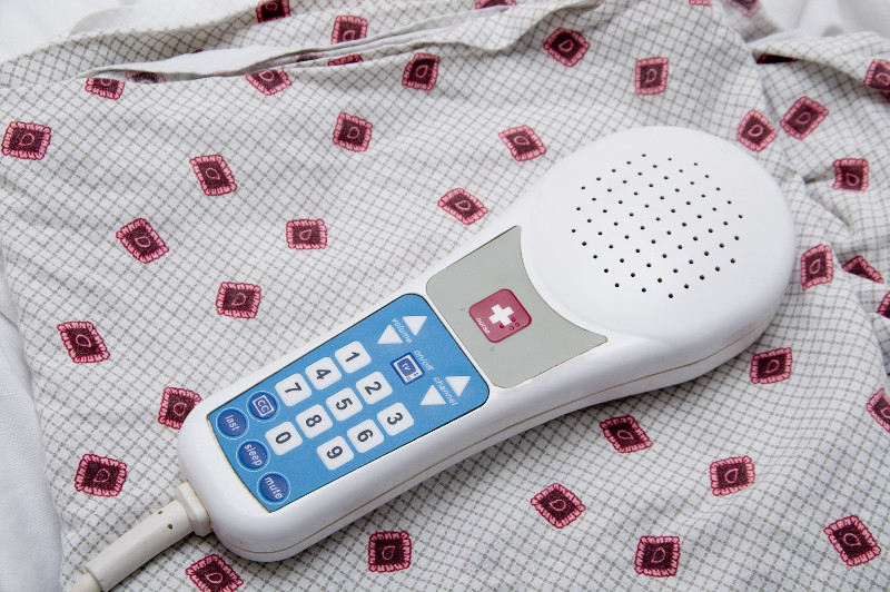
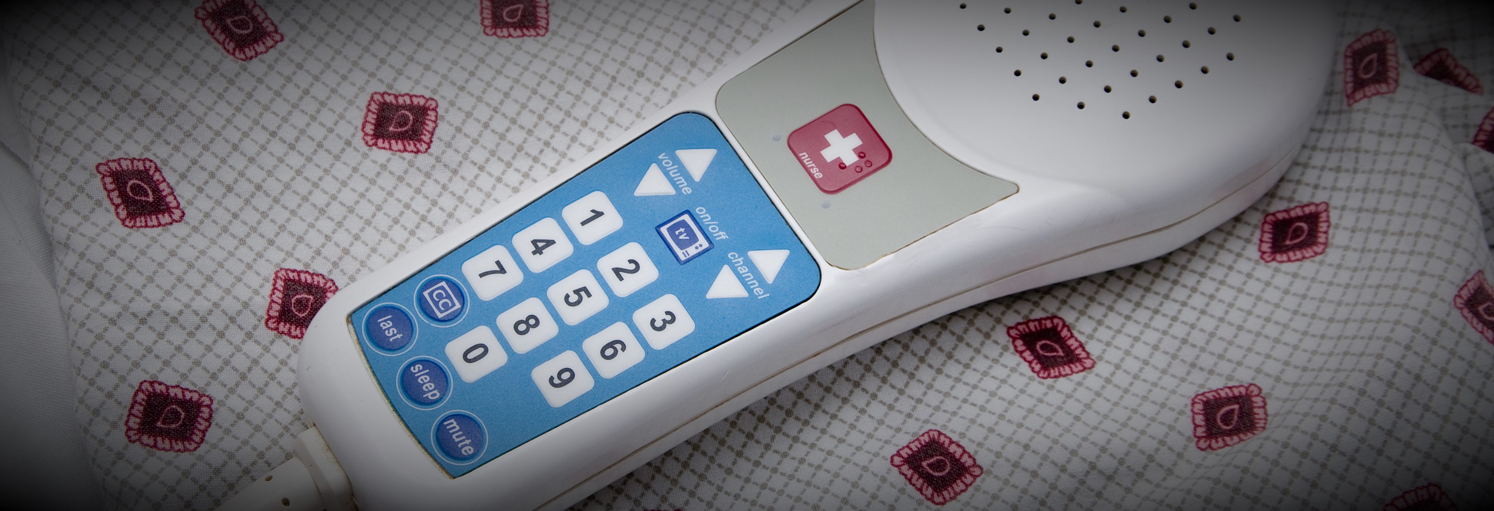
Our client manufactures hospital patient pendants used to control bed frame, nurse calling, and TV functions. The company was also growing after adapting a business model of being a repair depot for older designs for their own and the pendants of other manufacturers. As such, their products are very high mix and medium volume.
The basic functions for all these pendant models are closely related, so the client wanted a means to build a single automated test system that could verify functionality for 1000s of models. And, since the products are medical devices, the testers needed to comply to 21 CFR Part 820 and Part 11.
Solution
The testers were designed to support the common measurements needed to test the circuitry of the devices as well as the complex signals required to drive TVs and entertainment systems. A test sequence editor was created which allowed the client to create as many test sequences as needed to test each specific pendant model by creating a list from pre-defined basic measurement steps configured for each specific measurement.
For example, each device had a power supply, the voltage of which needed to be tested. To test a specific model, a voltage measurement step was added to the model-specific sequence and configured with the upper and lower measurement limits for the power supply. The complete test sequence was created by adding and configuring other measurements test steps as needed. Each test step could also be configured with switch configurations to connect the measurement equipment, such as a DMM, to the proper pins on the device circuit board.
Using this configuration process, the client was able to support the testing of well over 1000 models without any programming. A separate application was developed to create these test sequences which were saved as XML and fed to the test system for selection and execution.
The test execution was managed by NI TestStand and the pre-defined common test steps were written in LabVIEW. The test sequences and test results were interfaced to the client SQL database which they used in their ERP system. This ERP system used the results produced by the test system to help manage the workflow of production, for example by assuring that all units had passed testing before being shipped. Part 11 compliance was handled through checksums used to check if results had been modified.
Benefits
- Test sequence editor used to develop and maintain tests for 1000s of device models
- Enabling our client to create test sequences without programming reduced overall development costs by about 50%.
- Test sequences and test results were stored in the client’s ERP SQL-compliant database for integration with manufacturing workflow
- Modular and common software developed for the test systems reduced the V&V effort during IQ & OQ by allowing testing of the test execution application separate from the individual test sequences.
System Overview
The automated test system was able to execute each test sequence in three different modes: engineering, service, and production. Each mode has been specifically designed for various departments throughout the manufacturing floor. Typically, the manufacturing engineer would verify the sequence by executing it in engineering mode. Once the test sequence parameters pass, it was then approved for production testing.
During actual product testing, an approved and digitally-signed test sequence is loaded and executed via the test sequencer, designed for automated production. During execution, test results are displayed to the operator and simultaneously pushed to a database. The automated test system produces a record for each tested device, indicating the disposition of each test step and the overall performance of the device. All result data are digitally signed and protected from tampering.
The architecture of the test system follows a typical client–server model.
All client stations communicate with a central ERP and SQL server and each computer is secured by applying operating system security. The SQL server contains all of the test definitions, device history records and results. Information from it can be queried at any time by quality engineers throughout the organization, assuming they have proper login access. This provides real time status about products ready for shipment. Also, other than the software running on the client stations, no other user has permission to write or modify any information in this database. The client is able to keep the server in a protected area separating it from the manufacturing environment while the client test stations are placed throughout the manufacturing area.
Surprisingly, there were only twelve test steps needed to uniquely configure and be combined to create sequences to test well over 2000 unique models. Test steps are capable of measuring basic resistance, current and voltage parameters as well as perform sound quality measurements and high speed digital waveform analysis. Several tests were designed to be subjective while others are fully automated and test to a specified acceptable tolerance. During configuration, each test step requires the manufacturing engineer to enter expected values and tolerance limits to define pass – fail status. Upon testing, the devices are attached to a generic interface connection box and the test system makes the appropriate connections and measurements.
| SOFTWARE FUNCTIONS |
|---|
| NI TestStand |
| Low-level measurement drivers to interface to a DMM, signal generator, switches, and data acquisition cards. |
| Measurement-based test steps |
| Test sequence execution |
| Test sequence management |
| User access management |
| Test report creation and management |
| Verification of test sequence content and ability of user to execute |
| Verification of the content of the test results |
| HARDWARE USED |
|---|
| NI PXI chassis and controller |
| NI PXI acquisition cards for analog measurements |
| NI PXI acquisition cards for digital input and output |
| NI PXI DMM for precision voltage and resistance measurements |
| Audio amplifier for speaker tests |
| INTERFACES / PROTOCOLS |
|---|
| Ethernet |
*- images are conceptual, not actual
Automated Manufacturing Test Systems for Medical Diagnostic Equipment
Automated Manufacturing Test Stands for Medical Diagnostic Equipment
Using NI PXI and LabVIEW as a common architecture for multiple test systems testing several subassemblies
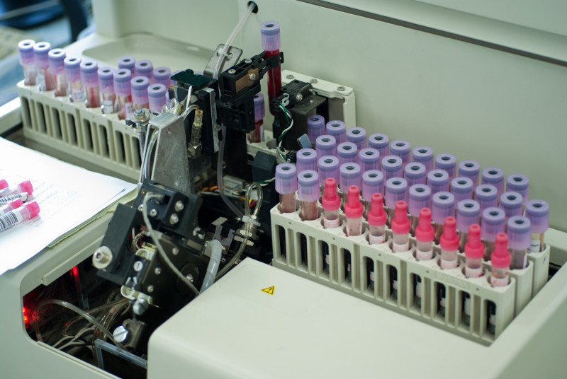
Client: a manufacturer of automated blood analysis machines
Challenge
Our client was embarking on a complete redesign of their flagship automated in-vitro Class 1 blood diagnostic machine. In order to meet schedule goals, the design and build of several automated test systems needed to occur in parallel with the overall machine. In a major design paradigm shift, many components of the machine were being manufactured as modular subassemblies, every one of which was an electro-mechanical device. Thus, multiple testers were required to test each of the specific subassemblies in the machine. And, since this was a medical device, the testers needed to comply to 21 CFR Part 820 and Part 11.
Solution
With a looming deadline, the testers needed a common architecture, so that all testers could leverage the development from the others. Since each subassembly could be tested independently of the overall machine prior to final assembly, the design of the testers was based on a common measurement and reporting architecture, written in LabVIEW, that interfaced to the customers Part 11 compliant database for testing procedures and measurement results. Furthermore, procedures and validation checks for calibration of the testers were part of the overall test architecture.
Benefits
- Modularization of the test system architecture aided development and maintenance
- Reduced overall development costs due to standardization of test sequence steps and reporting
- Both test sequences and test results were stored in a managed database that satisfied 21 CFR Part 11 requirements
- Modular and common software developed for the test systems reduced the V&V effort during IQ & OQ.
System Overview
Since multiple subassemblies were being tested, with one part-specific test system per part, the automated test systems used as much common hardware as possible to simplify the development effort through common hardware drivers and test steps. Test steps and the test executive that executed the test sequence(s) were developed using LabVIEW. Measurements were made with PXI equipment housed in a test stand along with support hardware.
The types of test steps required to verify the proper operation of each subassembly were categorized into basic operations, such as voltage reading, pulse counting, temperature reading, and communications with on-board microcontrollers. The specifics of each measurement could be configured for each of these measurement types so that each test step accommodated the needs of the specifics of each subassembly. For example, one subassembly might have needed to run the pulse counting for 2 seconds to accumulate enough pulses for accurate RPM calculation while another subassembly might have only needed 0.5 seconds to accomplish that calculation.
The configuration of a test step algorithm was accomplished via an XML description. The accumulation of these XML descriptions of each test step defined the test sequence run on that specific subassembly.
Test results were associated with these test sequences by completing the entries initially left blank in the test sequence, so that all results were explicitly bound to the test sequence.
The operator user interface distinguished between released and unreleased test sequences. With unreleased test sequences, engineers could try the most recent subassembly designs without needing to wait for final validation. The released sequences were only available to test operators. This login-driven branching was managed using the Windows login, so that the client employees could use their company badge-driven login process. Once logged in, the user would be able to execute the test sequence in automated mode, where all steps happen automatically, or manual mode, where one step could be operated at a time.
Furthermore, the Windows environment was locked down using built-in user account group policies to designate the level at which a user could access Windows or be locked into accessing only the test application.
V&V Effort
During the V&V effort, each test sequence was verified for expected operation, against both known good and bad parts. Once verified, the sequence was validated against the requirements and, when assured to be as expected, a checksum was applied to the resulting XML test sequence file and all was saved in a Part 11 compliant database. Upon retrieval, when ready to run a test, the sequence was checked against this checksum to assure that a sequence had not been tampered.
Test results, saved as XML in the same file format as the test sequence, were also surrounded by a checksum to verify that no tampering had occurred.
The IQ/OQ efforts were handled in a traditional manner with the client developing the IQ/OQ documentation, with our assistance, and then executing these procedures, again with our assistance.
| SOFTWARE FUNCTIONS |
|---|
| Low-level measurement drivers |
| Measurement-based test steps |
| Test sequence execution |
| Test sequence management |
| User access management |
| Test report creation and management |
| Verification of test sequence content and ability of user to execute |
| Verification of the content of the test results |
| HARDWARE USED |
|---|
| PXI chassis and controller |
| PXI acquisition cards for analog measurements |
| PXI acquisition cards for digital input and output |
| CAN card |
| INTERFACES / PROTOCOLS |
|---|
| Ethernet |
| CAN |
*- images are conceptual, not actual
Product Validation using LabVIEW RT & LabVIEW FPGA – Electromechanical Actuator Test Stand
Product Validation using LabVIEW RT & LabVIEW FPGA – An electromechanical test stand for an aerospace actuator
Automated testing reduces operator man hours and increases production throughput.
Client – A manufacturer of actuators in the mil-aero industry.
Challenge
New Product Introduction (in this case a new controller and new actuators) drove the need for a new aerospace electromechanical test stand.
Solution
New NI PXI-based electromechanical test equipment provided automated HIL testing, report generation, and SPC data generation. The sequencing of the test procedure, reporting, and verifiable results were managed with the StepWise test executive platform.
Benefits
- Automated testing reduces operator man hours and increases production throughput.
- Meets strict customer requirements regarding testing and data recording in a verifiable manner.
- Automated Test Report Generation.
- Collects data to support SPC (Statistical Process Control).
- Ability to interact with the internal state of the controller FPGA via the LVDS communication link.
System Overview
Viewpoint developed the software and selected NI data acquisition and control hardware for the test stand. There are several layers of software functionality. Also, the modularity of the test stand hardware assures maintainability for future upgrades and reduction of potential obsolescence issues, especially since the “programmability” of the FPGA-based HW allows repurposing via LabVIEW FPGA.
| HOST LABVIEW SOFTWARE LAYER |
|---|
| Test sequencer |
| Test steps (e.g. Frequency Response, Step Response, Dynamic Stiffness, Fault Response, Power Consumption) |
| Test Report Generator |
| GUI |
| REAL-TIME (RT) LABVIEW SOFTWARE LAYER |
|---|
| Data acquisition |
| 1553 comms |
| Function generator |
| Error detection |
| ESTOP |
| LABVIEW FPGA SOFTWARE LAYER |
|---|
| Synch data from 3 sources (tester, UUT, external DAQ device) |
| Stream high-speed data to disk |
| Stream high-speed data to analog outputs for HIL test |
| Custom communication protocol used by UUT over LVDS lines |
| HARDWARE RECOMMENDED |
|---|
| NI PXIe |
| NI FlexRIO card with LVDS adapter module |
| Multiple NI R Series cards |
| High speed, high voltage, isolated analog input cards |
| INTERFACES / PROTOCOLS |
|---|
| MIL-STD 1553 bus |
| LVDS |
| Ethernet |
| Custom TCP/IP |
*- images are conceptual only, not actual
Creating an N-Up Tester to handle increased production volume demands
Creating an N-Up Tester to handle increased production volume demands
Enhanced throughput offers ROI payback period of less than 1 year
Client
Automotive Components Supplier / Manufacturer
Challenge
The company makes automotive components in very large volume, several part models each at more than 1 million per year.
The client’s primary concern was conserving floor space. They were completely out of spare manufacturing space.
Solution
Viewpoint created an N-up NI PXI-based Manufacturing Test System. In this case, N=6 because analysis showed that a 6-up electronic part tester allowed the test operator to cover the test time with the load/unload time.
At the high volumes needed, the client needed to parallelize as much as possible. The cost of 6 sets of test equipment and device sockets was less important than speed. Using the equation:
ProfitPerUnit x NumberAdditionalPartsPerYearAfterParallelizing > CostOfTestEquipment,
being able to completely parallelize made the number of extra units per year large enough that the payback time for completely duplicating the measurement instrumentation for each UUT socket was less than about 1 year.
Benefits
- Paid for itself in less than 1 year by the enhanced throughput.
- This approach consumed about 20% the floor space that would have been used for duplicating the test system 5 more times (for a total of 6 testers)
System Overview
Viewpoint developed an NI TestStand application that ran 6 instances of the test sequence independently of each other utilizing the duplicated PXI-based test equipment. The common parts of the overall master sequence were:
- Startup check for the entire test stand
- Shutdown of the entire test stand
- Archiving the test results into the database
Part handling was managed by a PLC and robot which delivered the parts from a tray into the UUT sockets. Digital bits were used for signaling the test sequence which parts were present in their sockets and ready to test.
| SOFTWARE FUNCTIONS |
|---|
| Test System GUI |
| Test sequencer |
| Startup checker |
| Test Results Archiver |
Hidden Factory Assessments Lead to Waste and Cost Reductions

Sharing Business and Test Data Enables Efficiency Improvements
Reduce Production Costs by Coordinating Business and Test Data
Client: A major manufacturer of aerospace components
Problem Scope
Many companies operate in a high-mix, low-volume manufacturing environment. In these situations, production of such parts is often complex, with long assembly and test procedures describing the process to make and verify the part. Discussions of automating any part of these processes are often dismissed because an automated test system is thought to be expensive, especially an aerospace test system which requires significant documentation and acceptance testing efforts. Plus, it’s often erroneously thought that each part needs a unique test system.
Challenge
Our client wanted to improve their capability to manage the assembly procedures and get clarity on the status of any parts, whether partially or fully assembled. The existing situation had data manually-entered into a database form or even handwritten data that needed to be transcribed into a database. Often the database was local to the assembly cell. The chance for error was significant and the lag between data collection and updating the database was often days. When questions arose about the status of a particular unit, many hours could be spent in locating and evaluating the associated forms and paperwork.
The steps needed to achieve these goals were clear: automate the collection data on each part while being assembled so that those results would appear in a business-level database which would give a plant-wide view of the status of all the parts in progress.
Thus, this project needed to allow read/write access to sections of the Manufacturing Enterprise System (MES) database so that information about a part being assembled could be obtained automatically and results could be submitted to that MES database automatically.
Solution
We designed the PXI-based system based on the StepWise test executive platform to automate the assembly and testing. This platform enables two significant changes. These changes were made at each assembly cell by having the operator use a test PC and perhaps some measurement equipment as appropriate for the part(s) being assembled at that cell.
First, we replaced all the printed assembly procedures with electronic records so that any operator could review the latest version of the work instructions on a computer screen. This approach helped with version control, especially important since the client had various model revisions that came through the factor for rework, each with slightly different versions of assembly instructions.
Second, we displayed those electronically documented work procedures as steps in a test executive, allowing the results of each step in the assembly procedure to be captured electronically. When an assembly step was purely manual with no measurements, the fact that step was completed would be recorded, along with information such as the name of the operator performing the step, the duration that the step took, and so on. When a step required a measurement to be made, such as a functionality verification or a calibration result, the measurement would be collected. If the equipment making that measurement could be automated, we would collect that data automatically, and not require the operator to type the result into a computer form.
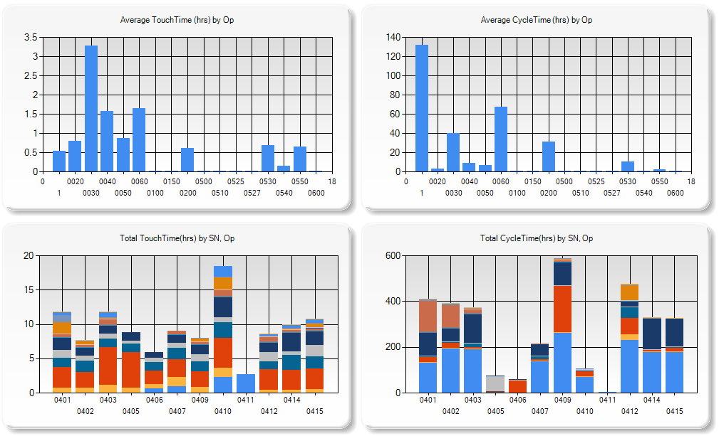
The outcome of this effort has enabled the client to get a snapshot of the status of parts in assembly, i.e., Works in Progress (WIP), quickly and accurately.
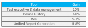
After these changes were made, many additional capabilities are now available with the advent of purpose-built queries into the appropriate MES database tables. The table below shows the overall efficiency gains achieved.
The key is the combination of the electronic test results obtained at the test equipment with information on work orders and manufacturing flow held in the various tables in the business MES database. This improvement happens even with manual or semi-automated test systems, and does not require a completely automated assembly and test system. Thus, the cost of the test system is much less than usually expected and, hence, the benefits are more easily cost-justified.
Manufacturing Test – for mission-critical components

Manufacturing Test – for mission-critical components
Using PXI & LabVIEW RT
Client: A major manufacturer of implantable cardiac and neural stimulators
Challenge
Our client needed several extremely reliable test systems to test the batteries that power their implantable medical devices. These new test systems were needed for two main reasons. First, the needed to upgrade existing obsolete test equipment, based on antiquated hardware and software. Second, new battery designs could not be tested on the old equipment.
A critical aspect of the new test system was the need to detect any excessive charge being extracted from the battery, thus rendering it unsuitable for surgical implantation. Thus, the test system needed to monitor the total energy withdrawn from a battery during testing to assure that it never exceeded a certain limit while also offering precise control of the type of pulses being drained from a battery.
All test results had to be stored in a database in order to maintain device history for each battery manufactured for archiving, quality control, and process improvements.
Solution
The updated manufacturing test system is PXI-based along with a custom micro-controller-based circuit board for some low-level control. Each PXI controller communicated to the microcontroller (uC) on the custom PCB via CAN. The uC controlled the current drain from the battery while monitoring actual current and voltage from the battery at over 1000 samples per second using a precision 6.5 digit PXI DMM. Additionally, each PXI chassis was used to test many hundreds of batteries. Signal connections were handled by several switch multiplexers. Overall control of all the PXI testers was managed by a host PC connected to the PXI controller.
Benefits
- Reduced test system cost vs complete COTS solution with combo LabVIEW RT on PXI and firmware on microcontroller-based custom circuit board
- Enabled tight control of DUT operation on controller with microsecond level responsiveness while being supervised by higher-level PXI RT
- Quick-reaction test abort capability
- Test results stored to database for archiving, quality control, and process improvements
System Overview
In a simplified view, the testing proceeded by pulsing the battery with a series of different durations and varying amperages. The exact sequence of this pulsing is unique for each DUT model. Measurements were made using a PXI filled with various NI boards such as DMMs, for accuracy, and data acquisition cards, for general purpose use.
Additionally, the pulsing amperage levels needed to be tightly controlled in order to know that the tests have been performed properly. Thus, a real-time amperage control scheme had to be implemented to maintain the level requested for the pulse. We chose to accomplish this control via an analog control circuit developed using a custom Viewpoint-developed circuit board. This board was controlled via a Microchip PIC microprocessor. The LabVIEW RT application communicated with the microcontroller to setup the pulsing sequence and coordinate the start and stop of the pulsing and the NI acquisition hardware.
This custom circuitry also reduced the overall cost of the test system by about 40%.
The engineering time to design this custom circuitry was more than offset by the reduction in material costs because more than 10 test systems were deployed, allowing the non-recurring engineering effort to be shared between many systems.
When no critical issues were detected, the waveforms acquired by the PXI system were stored and then analyzed to determine the viability of the DUT. The pass/fail disposition, the waveforms, the total energy consumed, and other test results were then passed along to a host supervisory PC that managed all these results in a database for archiving, quality control, and process improvements, each set of results being tied to the unique unit serial number.
The test systems provided reliable operation for testing the large annual production volumes of the mission-critical DUTs.
Since we designed the system to interface to our customer’s host supervisory PC via ethernet-based commands, the verification and validation (V&V) process could be supported by our customer in their Installation and Operational Qualification (IQ/OQ) efforts. Specifically, they wrote the IQ/OQ procedures around software that emulated interfacing with the host supervisory PC. This approach allowed them to automate parts of the V&V thus saving them almost 1 week of effort.
| SOFTWARE FUNCTIONS |
|---|
| LabVIEW RT – for managing the microcontroller functions and overall data collection and safety monitoring |
| Microcontroller application – to provide precision pulsing of the batteries |
| Communicate to the host PC – to both receive pulsing instructions and configurations and to return pulse waveforms for each battery tested. |
| MAIN HARDWARE COMPONENTS |
|---|
| PXI chassis & controller |
| PXI DMM |
| PXI analog input modules |
| SCXI multiplexing switches |
| INTERFACES / PROTOCOLS: |
|---|
| Ethernet TCP-IP |
| CAN |
Improving Efficiency in Industrial Manufacturing Test

Improving Efficiency in Industrial Manufacturing
Simplifying Report Generation for High-Mix, Low-Volume Industrial Servo Valve Tests
Client: A major industrial servo valve manufacturer
Challenge
A manufacturer of components for both commercial and military aircraft built a large number of different models of servo valves. Some models were made only a few times each year, while other models were made with an order of magnitude higher volume. Each unit underwent rigorous testing during and after assembly.
Our client needed to submit the results of that testing to their customers but since the production and testing of each unit happened in many locations, possibly even around the world, many hours were spent locating the appropriate datasets and assembling the report.
Furthermore, our client wanted to improve their responsiveness to requests from their customers by having rapid retrieval of the test report for any part after it had been delivered into the field.
Solution
Since the test datasets were varied due to the large numbers of different valve models and associated test procedures, a database was created using a platform based on the Resource Description Framework (RDF). An RDF database can accept arbitrary types of data, manage that data through metadata tags, and adjust gracefully to changes in content and shape of the connections between objects in the database.
This adaptability was key to our client being able to leap past some of the issues in standard SQL-based relational databases.
The results from each test run on each part at each (PXI-based) test system were tagged with metadata and pushed into the RDF database. The StepWise test executive platform interfaced to the RDF database by outputting XML content which was scanned by a routine created for the RDF database and converted into the RDF data and links. The part ID was a critical tag since this allowed searching the RDF database for all results associated with that specific part. This database resided on a server at the client’s headquarters and accepted data from worldwide locations.
Once the data for each part was housed in the database, a report could be generated. To accommodate the variety of data in that report, web technology was used to render the report pages based on the types of data entered into the database, as described by the metadata tags. For example, data identified as waveforms could be plotted or listed in tabular format. Having reports rendered based on the data types made it possible to handle adjustments to the types of data measured by the test system.
Results
With the ability to render reports quickly, our client could produce detailed reports for their customers indicating the performance of any specific requested servo valve.
Our client was able to trim the time to create reports to less than 1 day from the previous effort of 3-5 days and with less error.
- Data are now organized uniformly, simplifying the location of desired information, as compared with files stored on various test PCs and file servers.
- The client has the ability to generate automatic emails to their customers with the required reports already attached and ready to go.
- In potential warranty and customer service situations, having the ability to send the customer a report within hours represented great customer service.
All these features are available consistently across worldwide manufacturing facilities, reducing training and maintenance of procedures. And, of course, the reports handle using metric or English units as appropriate for the end customer.
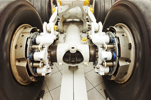
Decreasing Test Time for Aircraft Landing Gear

Decreasing Test Time for Aircraft Landing Gear
Endurance Testing for Aircraft Nose Landing Gear Steering
Client: A major manufacturer of aircraft landing systems
Challenge
A major manufacturer of aircraft landing equipment needed to develop a means of endurance and fatigue testing new designs for aircraft steering. The actuators involved in steering the nose landing gear (NLG) required precise and reliable control through thousands of steering cycles.
Control loops needed to be closed at faster than 1 ms.
Prior systems were handled manually without real-time control and monitoring.
Solution
Our customer designed and built a test rig to provide the hydraulics and environmental conditions for the endurance testing on the NLG. Viewpoint Systems supplied the electronic data acquisition and control hardware coupled with real-time software to provide the required fast control loops. The configuration and execution of the 1000s of steering cycles were managed by the same data acquisition and control system through a set of configuration screens that allowed specification of turn rates, min/max angles, drive and resistive torque settings, and so on. The flexibility offered with this HIL test capability mimicked the variety of conditions that the NLG would encounter in actual use.
- The various PID control loop configurations were also configurable along with gain scheduling required under different operating conditions.
- The environmental conditions were supported by controlling a temperature chamber through ramp and soak settings occurring during the steering tests.
- Measurements on the steering performance were collected from commanded setpoints, sensor readings, and controller outputs during the entire test run.
- Alarm and fault conditions, such as force exceedance, were monitored continuously during operation so that the system could safely run unattended.
Since the deployed solution was an aerospace test system, the entire system underwent an extremely rigorous acceptance testing procedure to verify proper and safe operation.
| SOFTWARE FUNCTIONS |
|---|
| Arbitrary Load and Position Profiles |
| Flight Position Control |
| Load Position/Force Control |
| Endurance/Flight Schedule Execution |
| Deterministic RT for DAQ and PID Control |
| HARDWARE |
|---|
| PXI/SCXI Hybrid RT Chassis |
| Discrete Pump Skid Interface |
| Custom Control Panel/Console |
| INTERFACES |
|---|
| Ethernet TCP/IP |
| SCXI |
Results
Prior to deployment of our system, setup of a test was much more manual and operators needed to be around to monitor operation.
With our new system, complete endurance testing could be specified and executed with minimal supervision. Furthermore, the tight integration of real-time control, HIL testing, and coordinated data collection made report creation much simpler than before.
The rigorous acceptance test gave trustworthiness to the data and allowed the design engineers to validate performance more quickly than the prior semi-automatic and manual methods of operation.
Setup of tests has been improved from prior operations. The endurance testing itself operated over a huge number of cycles lasting weeks to months between scheduled lubrication and maintenance.
The deployed system measures performance during the entire testing, even between the scheduled downtime.
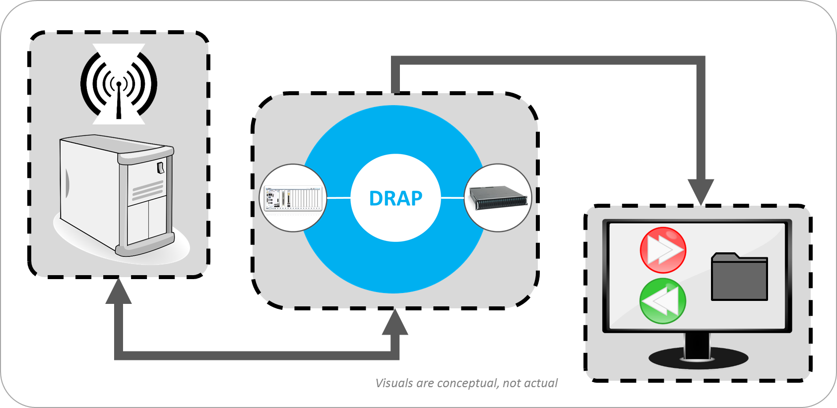
Digital Record And Playback – For a RF Receiver

Digital Record And Playback – For a RF Receiver
Collect hours of data at >1 GB/s
Client: A large high-tech R&D-oriented company.
Challenge
- Record hours of data at >1GB/s
- Play back digital test patterns for the RF receiver at real-time rates to understand bit-error rates
- Understand effects of RF chain prior to digitization
- Allow for platform to assist with algorithm development, debug and optimization
Solution
We utilized off-the-shelf hardware combined with custom software and had a working system after ~7 man-weeks of effort. The AEDIS system records and plays back digital data only, with A/D conversion being handled by the DUT. The system was developed on the National Instruments PXI Express platform. A RAID array of disks is used to continuously record data. Data manipulation is performed on a Xilinx Kintex-7 FPGA that forms the basis of a National Instruments High Speed Serial board. The AEDIS system is connected to the RF receiver using standard SFP+ connectors. A UI connects to the system locally or over Ethernet to monitor and control AEDIS during record/playback. The customer can also control the system via an API so that it can be integrated into a larger test system.
Benefits
- Allows for repeatable data through the processing chain.
- Can re-sample data, inject new headers into data packets, and re-pack new data.
System Overview
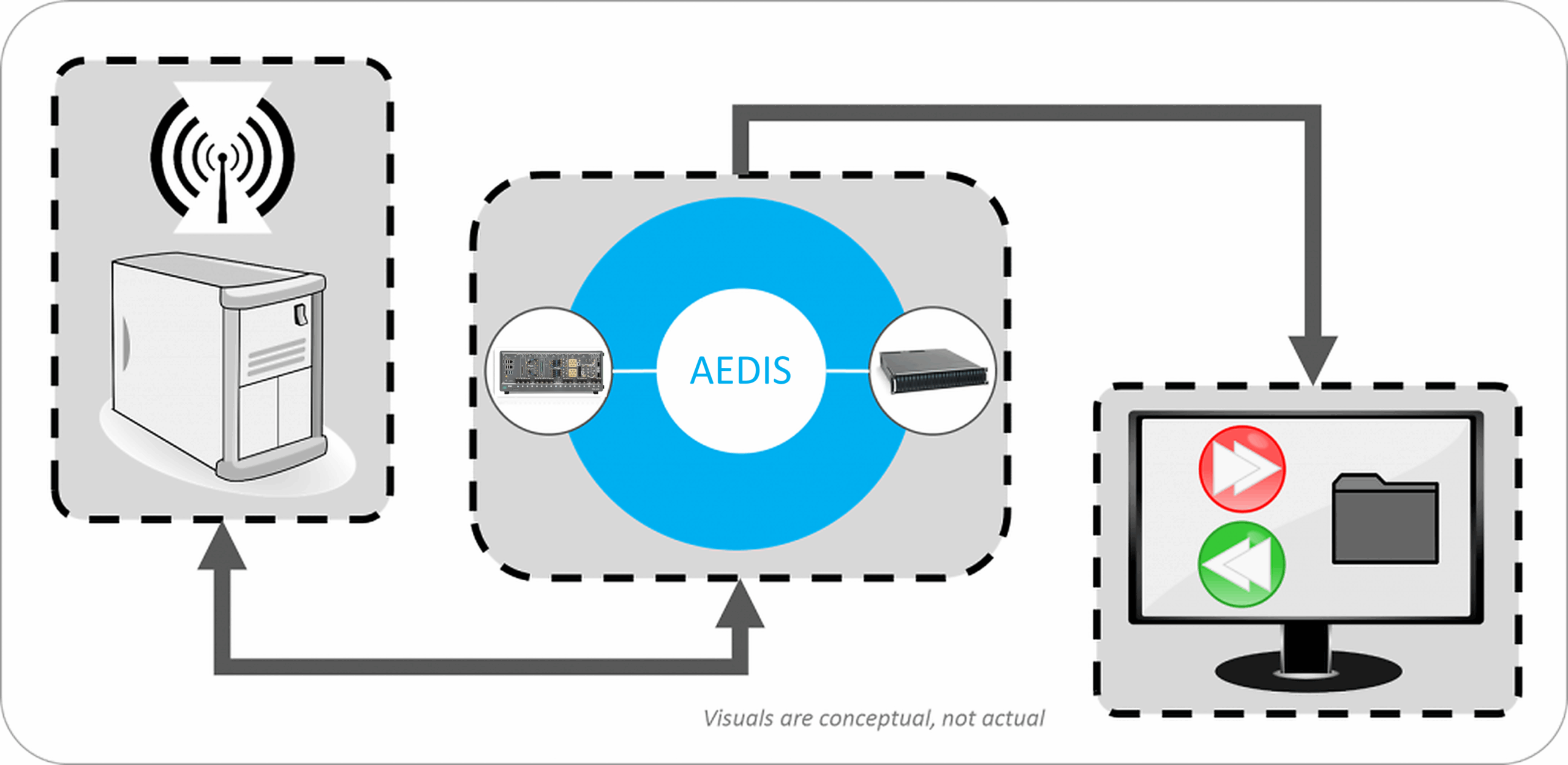
We’ve helped teams at some of the world’s most innovative companies


Viewpoint Systems Industry Expertise

Manufacturing

Energy

Mil-Aero
Transportation