LabVIEW Consultants / LabVIEW Programming Services | LabVIEW System Integration
US-based manufacturers: Need a LabVIEW Expert?
Need some existing code updated? Need a whole new LabVIEW-based test system?
While we go by many names (e.g. LabVIEW experts, LabVIEW system integrators, LabVIEW consultants, LabVIEW specialists, LabVIEW programmers, LabVIEW developers), the key takeaway is that we can take the software development and hardware integration off your plate.


Capabilities & Expertise (LabVIEW and NI hardware related)
We have one or more:
Certified LabVIEW Architect
Certified LabVIEW Developer
Certified TestStand Architect
Certified TestStand Developer
Talk to a LabVIEW Consultant. |
|---|
We’ve helped teams at some of the world’s most innovative companies


Testimonials
“Very impressed…kudos to Viewpoint”
I really want to thank you for all your help getting us to this stage in automating our testing. We had our customer in this week to oversee some testing and they were very impressed, which is definitely kudos to Viewpoint.
“Significant value”
The Viewpoint team provides significant value to our projects, and I really enjoy working with Viewpoint.
“Valuable part of our global team”
I have been working with Viewpoint for 15+ years on multiple projects. They have always provided creative and quick solutions to all of the problems we have placed in front of them. I have always considered them a valuable part of our global team.
LabVIEW Case Studies | Projects
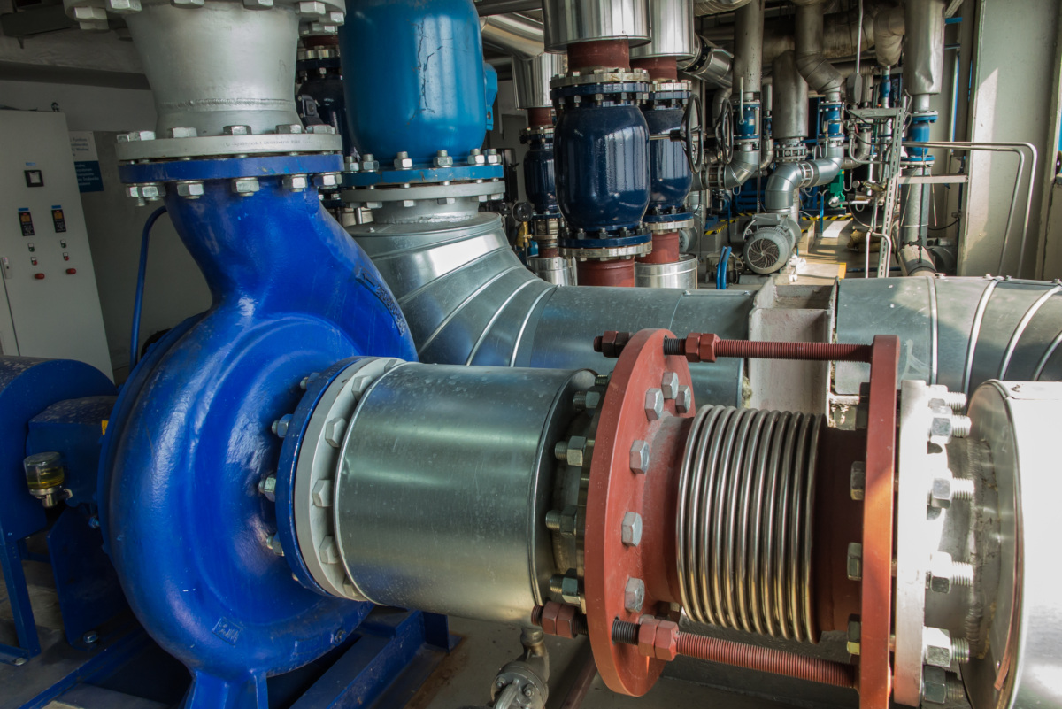
Pump Test Station
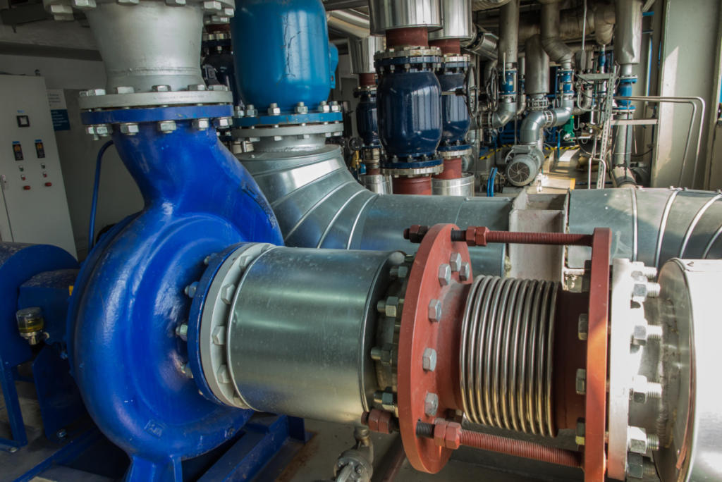
Pump Test Station
Client – Industrial pump manufacturer
Standardizing on testing technique & reporting
Reducing the number of pumps in the production queue
Challenge
Pump manufacturers typically test their product in the same facility in which the pumps are created. These tests are well defined and based on standards created by organizations such as API and ANSI to name a few. These tests are run to verify the performance of the pump as well as provide a report to the customer demonstrating that the pump they purchased will meet their needs. Sometimes these tests become factory witness tests where the customer sits in on the testing being performed on the pumps they had purchased.
Most pump manufacturers have more than one testing site at a facility to accommodate different pump types and sizes. The ability to automate these tests and to present a common look to the testing process and reports make the customer experience more positive to those reading the reports and/or witness the testing.
Our client came to us with the following requests:
- Evaluate the software written by the previous integrator to assess whether any of the code could be reused in the new application.
- Specify a hardware and software solution to acquire the signals needed to compute the performance results for standard tests. We made recommendations and selected appropriate hardware based on comments from our client about desiring compatibility between their test stands around the world.
- Deploy the hardware/software solution on the first test site to verify it performs as required and then deploy to the remaining test sites at their facility.
Solution
The Pump Test Utility had the following features:
- A Pump Test application that can run one of two different tests; a performance test and a net positive suction head (NPSH) test.
- An Access database was used to store the available sensors for that test site. The user selected the appropriate sensors while configuring the test.
- The test data was stored in an Excel file where each pump received its own Excel file.
- The LabVIEW Report Generation toolkit was used to populate the Excel file with data as well as create the report for the pump
Benefits
- Standardization of testing technique – now each pump will be tested with the same procedures and calculations/algorithms used are standardized across all test sites within the facility.
- Standardization of report content and presentation – now every customer that purchases a pump from our client will receive a report with identical information presented and that information will have been derived from the same calculations/algorithms.
- Reduction of the number of pumps in the production queue (and hence inventory) by roughly as much as 1/2 due to faster data acquisition and especially the archiving of the test results and the generation of the final report and its associated calculations.
System Overview
We developed the Pump Test Utility application to allow our client’s engineers and operators to:
- Run one of two guided tests that visually provides pump performance feedback during the test.
- Create a test configuration file based on an Excel template that will be used to store test data as well as generate a report.
The pump test software was developed in LabVIEW and interfaced with an Access database and Excel workbook to acquire the configuration information necessary to set up and run the required tests. The resulting data acquired during the test, both raw data acquired from the sensors and calculated data used to characterize the pump being tested, are saved to the Excel workbook. Both high speed (10 kS/s) and low speed (10 S/s) data are acquired and stored into one data file for archival storage and retrieval if additional analysis is required. The high-speed data are for vibration and sound measurements and low speed data are for pressure, temperature, RPM and flowrate measurements.
The pump test configuration is performed within the application from a series of drop down selections populated with sensors found in an Access database. The database is updated and maintained by the client through a series of user interfaces within the application. Once the test sensors and conditions have been selected, those selections are written to the Excel workbook for use in the reports.
The LabVIEW Report Generation Toolkit software was used to develop the reports the client provided to their customers. The Excel workbook template contained the formatting necessary for the reports. As the software wrote the data into the workbook, the reports were built from the formulas and formatting already configured in the Excel template. At the end of the test, the software printed the appropriate worksheets containing the elements of the report required.
| SOFTWARE FUNCTIONS |
|---|
| Data Acquisition |
| Test Sequencing |
| Metric or SAE Units |
| Multi-Level User Authentication |
| 2 Standardized Test Types |
| Generate Standard Table-Based Reports |
| Generate Pump Performance Graphs |
| Generate Vibration Graphs |
| Sensor Management Tools |
| Test Configuration Management Tools |
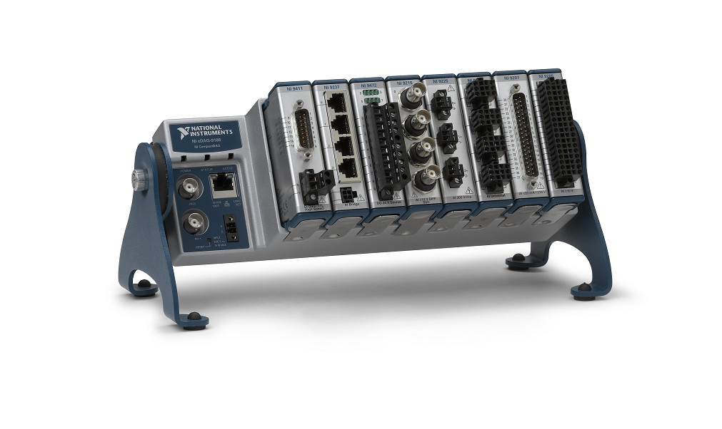
| HARDWARE USED |
|---|
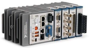
| NI cDAQ Signal Conditioning Chassis |
| Variety of NI cSeries Signal Conditioning Modules |
| Pressure Sensors |
| Flowmeters |
| Vibration Sensors |
| Displacement Sensors |
| Temperature Sensors |
| Torque Sensors |
| Speed Sensors |

Industrial Monitoring for a Harsh Environment
Industrial Monitoring for a Harsh Environment
Developing an industrial monitoring system for ultrasound-based sensing in a harsh environment
Client – Energy Research Lab
Challenge
Our client was experiencing problems making temperature measurements in a hostile, irradiated environment. Traditional temperature sensors don’t last long in this environment, so our client was developing a sensor designed for these conditions.
Special equipment is required to drive this sensor. It’s an active sensor requiring an ultrasound pulser/receiver (P/R) and high-speed digitizer to make it function.
The prior attempt the client made at using an original set of special equipment was having reliability and connectivity issues. This reduced reliability was of critical concern due to the requirement for the sensor to operate for years without downtime.
In addition, the existing application was incapable of displaying live data and lacked a user-friendly interface. On top of that, data analysis had to be done after the application was run, causing delays.
Our client needed reliable and robust hardware to drive the sensors and an application that would eliminate the challenges associated with the existing system.
Solution
Viewpoint accomplished the following:
- Evaluated two different ultrasonic P/R sensor driver hardware solutions to select a solution that would provide the connectivity robustness, configurability, and correct sensor driver characteristics required for the given sensors.
- Decoupled the digitizer embedded in the original P/R by adding a PXI digitizer with better capability.
- Provided backward compatibility with previous measurement hardware to aid in performance comparisons with the new hardware.
- Developed a LabVIEW-based application that corrected all the issues with the existing application including real-time data analysis, real-time data visibility and a modern user interface. The new application also provided sensor performance traceability using the sensor’s serial number.
We selected the NI hardware and non-NI equipment to assure compatibility.
Benefits
The enhanced measurement system offers the following benefits:
- Reliable sensor subsystem to ensure uninterrupted data acquisition.
- Measurement hardware configurability for sample rate, collection duration, and pulsing repetition rate.
- Application configurability for automating the analysis, historical archiving, and results reporting.
- Real-time data analysis.
- Sensor traceability through serial number and data files.
- Engineering mode to take control of the entire measurement system.
- Improved data logging to include raw and analyzed data.
- Improved application user experience via robust data collection and configurability.
System Overview
The deployed temperature monitoring system consisted of the following components:
- COTS pulser/receiver hardware for driving the sensors.
- COTS high-speed DAQ for retrieving ultrasound signals.
- A LabVIEW-based software application to provide real time data monitoring, error/alarm notification, data analysis, data logging, part traceability and backward compatibility with the older sensor driver hardware.
| SOFTWARE FUNCTIONS |
|---|
| Acquire Data from Sensor Driver Device |
| Data Analysis |
| Write Raw Data to File |
| Write Analyzed Data to File |
| Configuration Utility |
| HARDWARE UTILIZED |
|---|
| Sensor Pulser/Receiver Driver |
| NI PXIe Expansion Chassis |
| NI PXI Oscilloscope Module |
| NI PXI Thunderbolt 3 Module |
| INTERFACES / PROTOCOLS |
|---|
| RS-232 |
| Thunderbolt 3 |

Semi-Automation of an Optical Component Manufacturing Process
Semi-Automation of an Optical Component Manufacturing Process
Automation reduces waste, manufacturing cycle time and human error
Client – Optical component manufacturer of precision structured surfaces

Challenge
Our client needed to introduce automation to a highly manual manufacturing process for injection molding of precision components. The manual process was slow, and yields were low, causing excessive waste. The low yield was traced to the inability to control the critical process variables.
Solution
Viewpoint decided to integrate a PLC, a motion controller, and LabVIEW to develop a solution for a “first phase” automation system to replace the highly manual process.
The PLC:
- controls eight axes of motion,
- controls the UV light for curing,
- and interfaces to other process equipment such as valves and sensors .
The LabVIEW application:
- guides the operator through the manufacturing process step by step,
- interacts with the PLC,
- and displays real-time process data and log data to a file for further review post manufacturing.
Benefits
Besides the automation benefits of consistency and speed, the client wanted the ability to adjust configuration settings and limits for almost every aspect of the operation, such as setpoints and motion stage positions. Configuration screens were developed that let an operator run through the manufacturing steps manually while making adjustments on-the-fly; perfect for “dry-run” production simulations. These screens require special permissions to operate in engineering mode rather than production mode.
The other benefits are:
- Reduction of set-up cycle time increasing component throughput.
- Reduction of variability of the manufacturing process.
- Increased product yield resulting in reduced waste.
- Reduced probability of product contamination due to automation and cycle time reduction.
- Data files enable review of past manufacturing data and potential process improvements.
- Part traceability enables better process understanding and control.
- Prompts and machine status checks help guide novice operators.
- System is configurable for different product lines.
System Overview
The entire system consists of the following components:
- A PLC controlling the motors responsible for positioning the tooling and other process equipment.
- A standalone controller responsible for controlling the process temperature.
- A LabVIEW application to serve as the operator’s interface to the manufacturing process. The application is responsible for tasks including:
- Guide the operator through the process.
- Provide important information about the process to the operator.
- Display any warnings/alarms detected by the PLC.
- Write process data to a file.
| SOFTWARE FUNCTIONS |
|---|
| Read Data from Stand Alone Controllers |
| Read from, Write to PLC |
| Write Data to File |
| Comprehensive User Interface |
| Process Sequencer |
| HARDWARE UTILIZED |
|---|
| Stand Alone Temperature Controllers |
| PLC |
| Motion Equipment |
| Vision Equipment |
| INTERFACES / PROTOCOLS |
|---|
| RS-485 |
| OPC UA |
High-Speed Digital Subsystem Emulator
High-Speed Digital Subsystem Emulator
Client: A large company involved in C4ISR
At maximum throughput, the AEDIS systems needed to consume and produce more than about 800 MB/s/slot.
Background
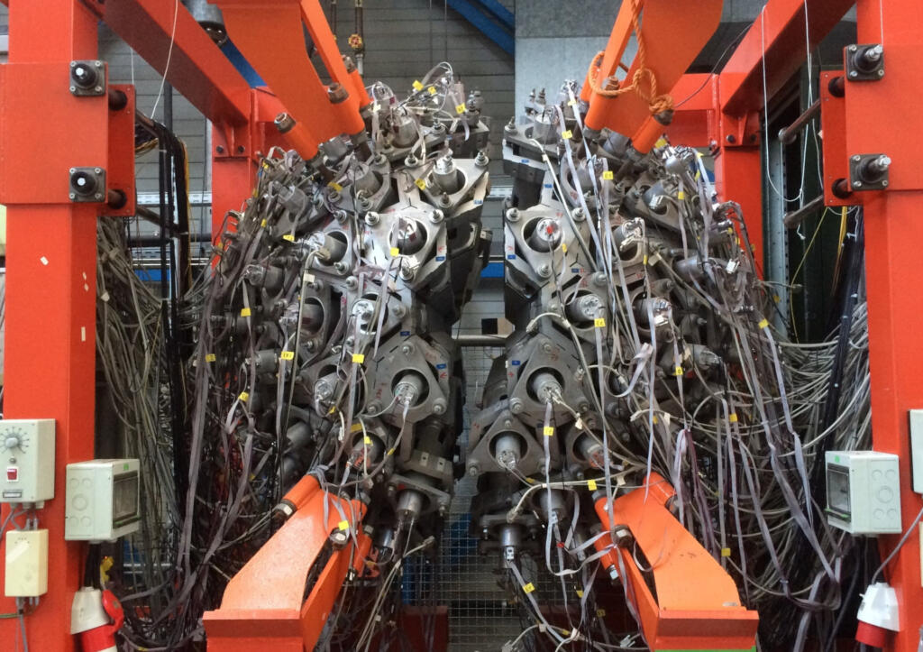
A large company involved in C4ISR was developing a system for a new high-speed digital sensor device. Viewpoint was contracted to build a test system used in design validation and ultimately endurance testing of the sensor. Since the sensor was a component of a larger system which was being developed at the same time, another test system was created to simulate the sensor by feeding signals into the system. This ability to use HIL testing for both the sensor and the downstream sensor electronics enabled parallel development, thus saving time and reducing schedule.
Challenge
Both the amount of data and the frequencies of the various digital signals were nearly at the limit of hardware capabilities. At maximum throughput, the systems needed to consume during record and produce during playback about 800 MB/s/slot. The FPGA clock on the FlexRIO had to run up to 300 MHz. The skew between triggers for data transmission needed to be less than 5 ns even between multiple FlexRIO cards even when the parallel data paths have inherent skews associated with the sensor. Finally, the systems needed to handle clocks that might be out-of-phase.
Achieving these requirements required significant engineering design in the face of multiple possible roadblocks, any one of which could have eliminated a successful outcome.
Furthermore, as usual, the development timeline was tight. In this case, it was a very tight 3 months. Basing the solution on our AEDIS platform was critical to meeting this challenge.
Viewpoint’s Solution
To meet the timeline, we had to work in parallel across several fronts:
- LabVIEW-based application development for both record and playback
- LabVIEW FPGA development for marshalling data between the controller and DRAM
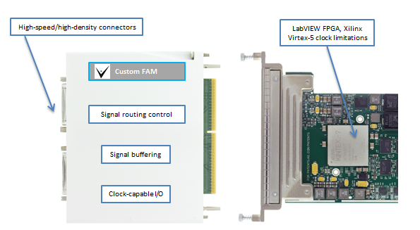
- Custom FAM circuit board design and build
- FlexRIO FPGA CLIP nodes and code for low-level data handling
Technical Highlights
This sensor had several parallel data paths of clock and data lines with clock speeds up to 300 MHz on each path requiring exacting design and build of a custom FlexRIO Adapter Module (FAM) and unique custom CLIP nodes for extending the FlexRIO FPGA capabilities. The FAM also had a special connector for interfacing to the customer’s hardware.
Additional NI hardware and software completed the system components.
Results
The choice to base the AEDIS emulators on NI hardware and software was critical to completing this project. The open architecture in both hardware (custom FAM) and software (CLIP Nodes) enabled us to include some very creative extensions to the base toolset without which the project would not have succeeded in the allotted pressured schedule and on a predetermined budget. We were able to stretch the capabilities of the hardware and software very close to their maximum specifications by combining COTS and custom much more cost effectively than a purely custom design. Further, with HIL tests, both the sensor and the sensor electronics could be developed in parallel, leading to a significant schedule buyback for our client.
LabVIEW Layers
The host application, written in LabVIEW, managed the configuration of the data acquisition and the control of the LabVIEW RT-based FlexRIO systems. The configuration primarily dealt with the number of sensor channels in use, skew settings between digital lines, and other parameters that dealt with the organization of the data passed between the sensor and the FlexRIO.
Two FlexRIO applications were written, one for record and one for playback. Each FlexRIO application was written in LabVIEW, and managed the configuration of the FlexRIO cards and the movement of data between the FlexRIO cards and the RAID drives. Note that Windows supported for the RAID driver. Between 10 and 32 DMA channels were used for streaming, depending on the number of sensor channels being used.
And, each FlexRIO application had an FPGA layer, written in LabVIEW FPGA enhanced with custom CLIP nodes. For the record application, we developed a custom DRAM FIFO on the FPGA to assist with the latencies on the PXIe bus. For the playback application, we were able to stream directly from DRAM.
FlexRIO Considerations
The FlexRIO and stock FAMs from NI were initially considered as candidates for this project. Clearly, working with commercial-off-the-shelf (COTS) components would be most effective. Three options were available at the project start which could accommodate the required clock frequencies, but none offered both the required channel counts and skew/routing limitations. Hence, we had to design a custom FAM. This decision, made before the start of the project, turned out to be wise in hindsight because the parallel development path resulted in some shifts of sensor requirements which could be accommodated with the custom FAM but might have led to a dead-end with a COTS FAM.
FlexRIO CLIP
In LabVIEW FPGA, a CLIP Node is a method to import custom FPGA IP (i.e., code) into a LabVIEW FPGA application. CLIP stands for Component-Level Intellectual Property. We needed to use special Socketed CLIP Nodes (i.e., VHDL that can access FPGA pins) for this project because we could expose additional features of the Xilinx Virtex-5 not exposed in LabVIEW FPGA by accessing Xilinx primitives. Some specific features were:
- Faster FPGA clocking
- Additional clocking options
- Individual clock and skew control
- Custom PLL de-jitter nodes
Essentially, the FPGA design had a majority of FPGA code developed in LabVIEW FPGA and we used CLIP Nodes for interfacing the signals between the FlexRIO and the FAM.
FlexRIO Adapter Module
As mentioned earlier, we had to create a custom FAM because of the need to route high speed signals from customer-specific high density connectors while synchronizing signals across multiple data channels and FPGA modules to within one (300 MHz) clock cycle.
At these high-speeds, the FAM needed careful buffering and impedance matching both on the signals as well internal components on the FAM PCB. At the start of the design, we utilized Mentor Graphics HyperLynx High Speed DDR signaling Simulation software to minimize signal reflections prior to building actual hardware. This step saved countless hours in spinning physical hardware designs.
We designed the FAM to allow channel routing and access to additional clock and trigger pins on the Xilinx chip and PXIe backplane.
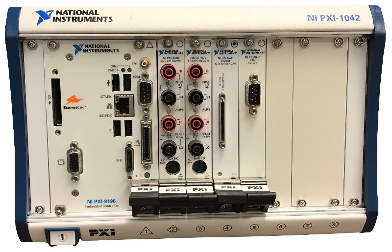
Custom Test System Using NI PXI for Electrical Test
Custom Test System Using NI PXI for Electrical Test
Updating an obsolete tester that maintains functionality
Client – Medical Device Manufacturer
Challenge
Our client already had a test system in place, but the tester (really two test systems testing two different product variants) was becoming obsolete. The tester was old, hardware was failing, and it was getting harder and harder to keep it reliably running. They wanted a new tester to improve reliability, but maintain the functionality of the existing tester to keep the FDA-mandated verification and validation time to a minimum.
Solution
The updated end-of-line manufacturing test system maintains the functionality of the old test systems, but with updated hardware and software. The same software is utilized for both the manual test system update and the automated test system update. Our client deployed 6 manual testers and 1 automated tester.
Benefits
- Improved maintainability and reliability with updated hardware and software
- Maintains existing test system functionality to keep certification time down
System Overview
There were two variants of the new test system. One was for an older product line that utilized manual test, with an operator that connected/disconnected the UUT, and initiated the test. The other was an automated tester, integrated into a manufacturing machine. Both testers utilized custom fixtures (provided by the client), off-the-shelf NI measurement hardware (selected by Viewpoint), and custom test software (developed by Viewpoint). The software is configurable for both the manual test system and the automated test system.
| SOFTWARE FUNCTIONS |
|---|
| Read UUT limits from config file |
| Perform tester self-test |
| Measure impedance |
| Power UUT |
| Pressurize UUT |
| Measure UUT output |
| Perform leak down pressure test |
| PLC interface (for automated tester) for start, done, pass, fail |
| HARDWARE USED |
|---|
| Custom test fixture (provided by client) |
| NI PXI |
| PXI Multifunction I/O Module |
| PXI Digital I/O Module |
| PXI Relay Module |
| PXI Digital Multimeter Module |
| PXI Switch Matrix Module |
*- images are conceptual, not actual
Manufacturing Inspection System Uses Machine Vision to verify assembly and labeling
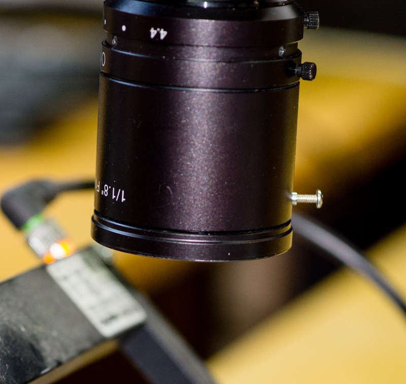
Manufacturing Inspection System Uses Machine Vision to verify assembly and labeling
Reducing human error with automated inspection
Client – Automotive Component Manufacturer
Challenge
Our client already had an end-of-line tester in place. However, preventing incorrect product shipments drove them to add machine vision capabilities to verify that the part being packed is of the correct physical configuration and that the part was labeled correctly. They also wanted a more automated way to track which serial numbers were being shipped.
Solution
Viewpoint enhanced the existing end-of-line tester by adding machine vision capabilities to verify correct part assembly and part labeling. This capability also allowed for automated tracking of which parts went into which shipping container.
Benefits
- Automated part assembly verification to reduce human error from manual visual inspection
- Automated label verification to reduce the chance of shipping the wrong product
System Overview
The enhanced system added machine vision-based capabilities to an existing end-of-line manufacturing test system. New hardware (cameras, lighting, fixture) was selected and integrated by the client. Viewpoint developed the image analysis routines using the Cognex In-Sight software. These routines were then downloaded and controlled using LabVIEW software developed by Viewpoint. In addition, the LabVIEW GUI contained the image acquired by the camera and the results of the image analysis. The tester can inspect four different part types.
The software essentially performs the following functions:
- Look up the expected characteristics of the part being inspected.
- Populate the on-camera In-Sight “spreadsheet” with configuration information used in the image analysis/inspection.
- Trigger the image capture and read results from the on-camera spreadsheet.
- Use the on-camera image analysis to check a critical angle of the part as the part is set in the nest fixture.
- Check the information laser etched on the part and compare the results with what should be on the part (relative to the barcode read in for the lot and the 2D barcode on the part) using the OCR/OCV capabilities of the camera.
- Perform other physical part characterization image analyses to verify the part was correctly labeled & assembled.
| SOFTWARE FUNCTIONS |
|---|
| Look up expected part characteristics |
| Trigger image capture |
| Read results of on-camera image analysis |
| Display image taken by camera and show if test passed or failed |
| Monitor contiguous part failures & initiate shutdown |
| Log vision test failures to database |
| HARDWARE USED |
|---|
| Existing end-of-line tester |
| Test Fixture |
| (qty 2) Cognex camera |
| Lighting for camera |
| INTERFACES / PROTOCOLS |
|---|
| TCP/IP |
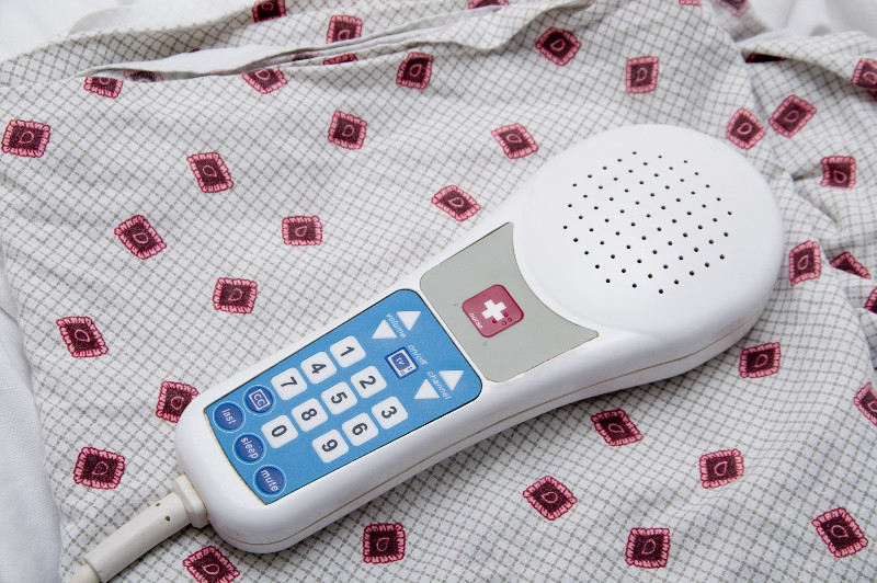
Automated Manufacturing Test System for Electronic Medical Devices
Automated Manufacturing Test System for Electronic Medical Devices
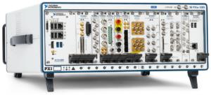
Using PXI and LabVIEW for modular testing of over 1,000 different models
Client – a medical device manufacturer and repair depot
Challenge
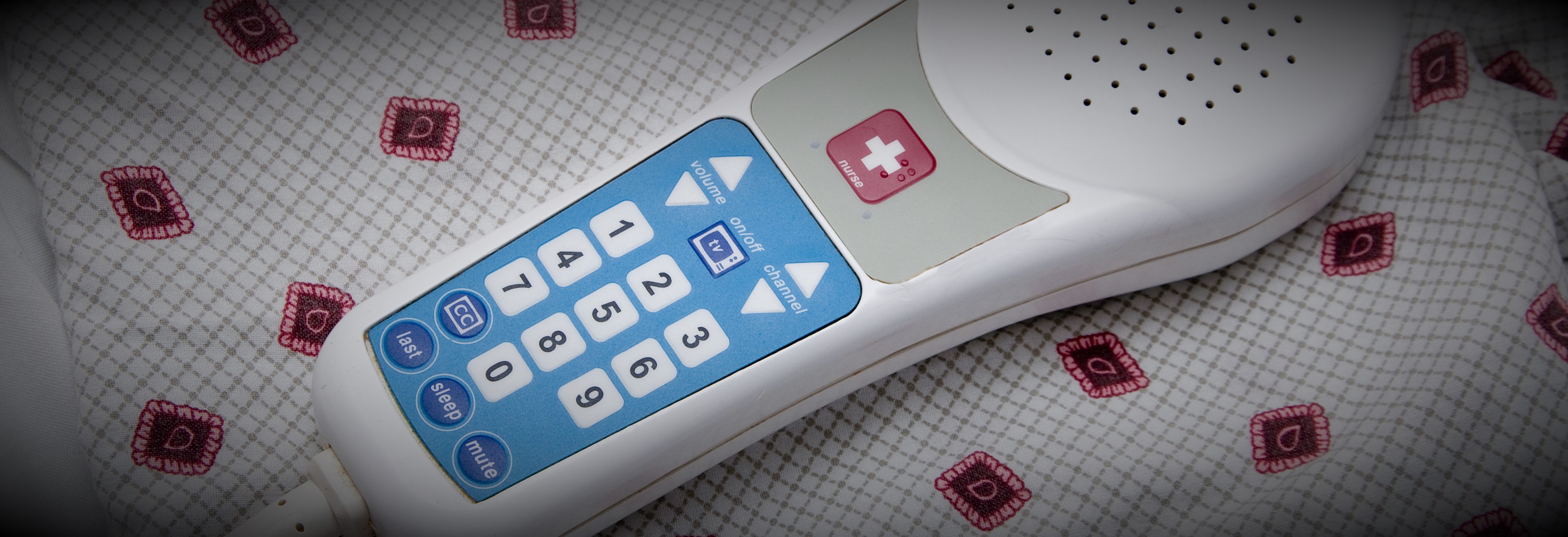
Our client manufactures hospital patient pendants used to control bed frame, nurse calling, and TV functions. The company was also growing after adapting a business model of being a repair depot for older designs for their own and the pendants of other manufacturers. As such, their products are very high mix and medium volume.
The basic functions for all these pendant models are closely related, so the client wanted a means to build a single automated test system that could verify functionality for 1000s of models. And, since the products are medical devices, the testers needed to comply to 21 CFR Part 820 and Part 11.
Solution
The testers were designed to support the common measurements needed to test the circuitry of the devices as well as the complex signals required to drive TVs and entertainment systems. A test sequence editor was created which allowed the client to create as many test sequences as needed to test each specific pendant model by creating a list from pre-defined basic measurement steps configured for each specific measurement.
For example, each device had a power supply, the voltage of which needed to be tested. To test a specific model, a voltage measurement step was added to the model-specific sequence and configured with the upper and lower measurement limits for the power supply. The complete test sequence was created by adding and configuring other measurements test steps as needed. Each test step could also be configured with switch configurations to connect the measurement equipment, such as a DMM, to the proper pins on the device circuit board.
Using this configuration process, the client was able to support the testing of well over 1000 models without any programming. A separate application was developed to create these test sequences which were saved as XML and fed to the test system for selection and execution.
The test execution was managed by NI TestStand and the pre-defined common test steps were written in LabVIEW. The test sequences and test results were interfaced to the client SQL database which they used in their ERP system. This ERP system used the results produced by the test system to help manage the workflow of production, for example by assuring that all units had passed testing before being shipped. Part 11 compliance was handled through checksums used to check if results had been modified.
Benefits
- Test sequence editor used to develop and maintain tests for 1000s of device models
- Enabling our client to create test sequences without programming reduced overall development costs by about 50%.
- Test sequences and test results were stored in the client’s ERP SQL-compliant database for integration with manufacturing workflow
- Modular and common software developed for the test systems reduced the V&V effort during IQ & OQ by allowing testing of the test execution application separate from the individual test sequences.
System Overview
The automated test system was able to execute each test sequence in three different modes: engineering, service, and production. Each mode has been specifically designed for various departments throughout the manufacturing floor. Typically, the manufacturing engineer would verify the sequence by executing it in engineering mode. Once the test sequence parameters pass, it was then approved for production testing.
During actual product testing, an approved and digitally-signed test sequence is loaded and executed via the test sequencer, designed for automated production. During execution, test results are displayed to the operator and simultaneously pushed to a database. The automated test system produces a record for each tested device, indicating the disposition of each test step and the overall performance of the device. All result data are digitally signed and protected from tampering.
The architecture of the test system follows a typical client–server model.
All client stations communicate with a central ERP and SQL server and each computer is secured by applying operating system security. The SQL server contains all of the test definitions, device history records and results. Information from it can be queried at any time by quality engineers throughout the organization, assuming they have proper login access. This provides real time status about products ready for shipment. Also, other than the software running on the client stations, no other user has permission to write or modify any information in this database. The client is able to keep the server in a protected area separating it from the manufacturing environment while the client test stations are placed throughout the manufacturing area.
Surprisingly, there were only twelve test steps needed to uniquely configure and be combined to create sequences to test well over 2000 unique models. Test steps are capable of measuring basic resistance, current and voltage parameters as well as perform sound quality measurements and high speed digital waveform analysis. Several tests were designed to be subjective while others are fully automated and test to a specified acceptable tolerance. During configuration, each test step requires the manufacturing engineer to enter expected values and tolerance limits to define pass – fail status. Upon testing, the devices are attached to a generic interface connection box and the test system makes the appropriate connections and measurements.
| SOFTWARE FUNCTIONS |
|---|
| NI TestStand |
| Low-level measurement drivers to interface to a DMM, signal generator, switches, and data acquisition cards. |
| Measurement-based test steps |
| Test sequence execution |
| Test sequence management |
| User access management |
| Test report creation and management |
| Verification of test sequence content and ability of user to execute |
| Verification of the content of the test results |
| HARDWARE USED |
|---|
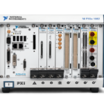
| NI PXI chassis and controller |
| NI PXI acquisition cards for analog measurements |
| NI PXI acquisition cards for digital input and output |
| NI PXI DMM for precision voltage and resistance measurements |
| Audio amplifier for speaker tests |
| INTERFACES / PROTOCOLS |
|---|
| Ethernet |
*- images are conceptual, not actual
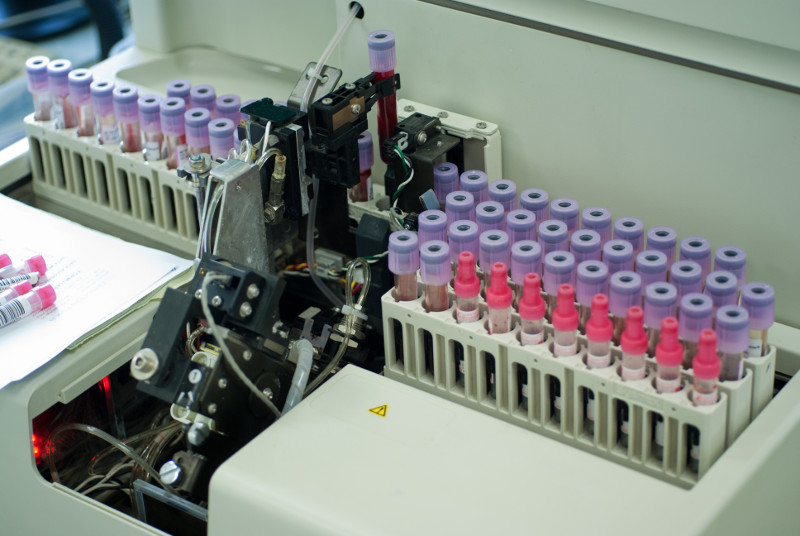
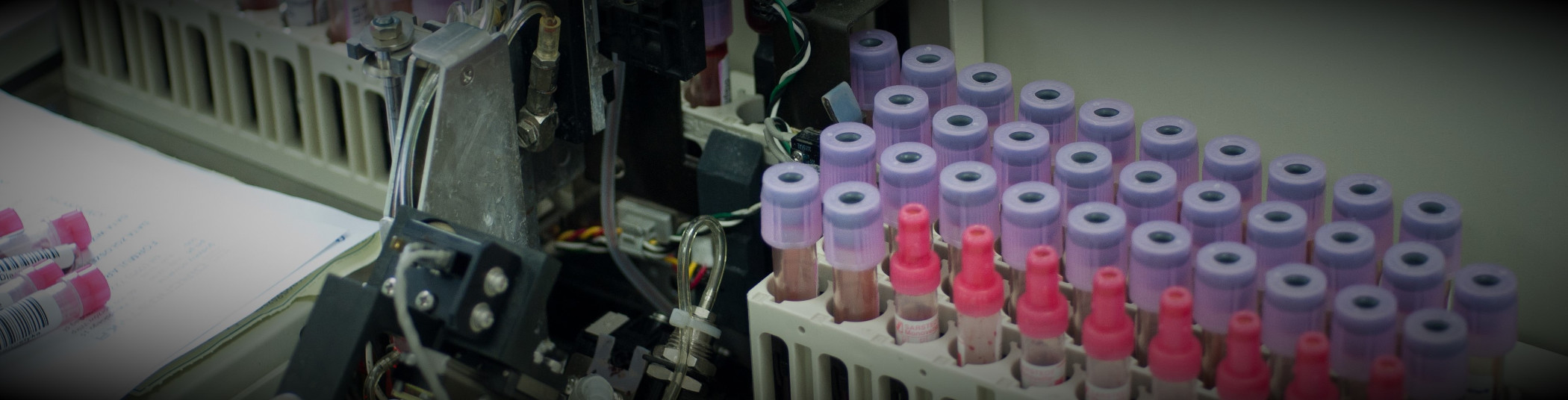
Automated Manufacturing Test Systems for Medical Diagnostic Equipment
Automated Manufacturing Test Stands for Medical Diagnostic Equipment
Using NI PXI and LabVIEW as a common architecture for multiple test systems testing several subassemblies
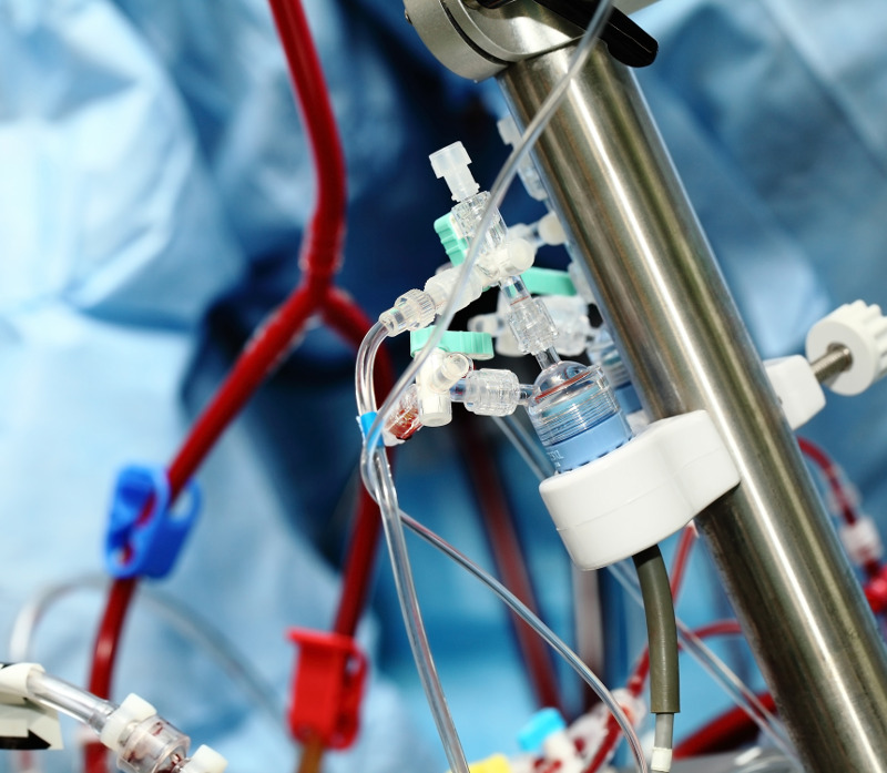
Client: a manufacturer of automated blood analysis machines
Challenge
Our client was embarking on a complete redesign of their flagship automated in-vitro Class 1 blood diagnostic machine. In order to meet schedule goals, the design and build of several automated test systems needed to occur in parallel with the overall machine. In a major design paradigm shift, many components of the machine were being manufactured as modular subassemblies, every one of which was an electro-mechanical device. Thus, multiple testers were required to test each of the specific subassemblies in the machine. And, since this was a medical device, the testers needed to comply to 21 CFR Part 820 and Part 11.
Solution
With a looming deadline, the testers needed a common architecture, so that all testers could leverage the development from the others. Since each subassembly could be tested independently of the overall machine prior to final assembly, the design of the testers was based on a common measurement and reporting architecture, written in LabVIEW, that interfaced to the customers Part 11 compliant database for testing procedures and measurement results. Furthermore, procedures and validation checks for calibration of the testers were part of the overall test architecture.
Benefits
- Modularization of the test system architecture aided development and maintenance
- Reduced overall development costs due to standardization of test sequence steps and reporting
- Both test sequences and test results were stored in a managed database that satisfied 21 CFR Part 11 requirements
- Modular and common software developed for the test systems reduced the V&V effort during IQ & OQ.
System Overview
Since multiple subassemblies were being tested, with one part-specific test system per part, the automated test systems used as much common hardware as possible to simplify the development effort through common hardware drivers and test steps. Test steps and the test executive that executed the test sequence(s) were developed using LabVIEW. Measurements were made with PXI equipment housed in a test stand along with support hardware.
The types of test steps required to verify the proper operation of each subassembly were categorized into basic operations, such as voltage reading, pulse counting, temperature reading, and communications with on-board microcontrollers. The specifics of each measurement could be configured for each of these measurement types so that each test step accommodated the needs of the specifics of each subassembly. For example, one subassembly might have needed to run the pulse counting for 2 seconds to accumulate enough pulses for accurate RPM calculation while another subassembly might have only needed 0.5 seconds to accomplish that calculation.
The configuration of a test step algorithm was accomplished via an XML description. The accumulation of these XML descriptions of each test step defined the test sequence run on that specific subassembly.
Test results were associated with these test sequences by completing the entries initially left blank in the test sequence, so that all results were explicitly bound to the test sequence.
The operator user interface distinguished between released and unreleased test sequences. With unreleased test sequences, engineers could try the most recent subassembly designs without needing to wait for final validation. The released sequences were only available to test operators. This login-driven branching was managed using the Windows login, so that the client employees could use their company badge-driven login process. Once logged in, the user would be able to execute the test sequence in automated mode, where all steps happen automatically, or manual mode, where one step could be operated at a time.
Furthermore, the Windows environment was locked down using built-in user account group policies to designate the level at which a user could access Windows or be locked into accessing only the test application.
V&V Effort
During the V&V effort, each test sequence was verified for expected operation, against both known good and bad parts. Once verified, the sequence was validated against the requirements and, when assured to be as expected, a checksum was applied to the resulting XML test sequence file and all was saved in a Part 11 compliant database. Upon retrieval, when ready to run a test, the sequence was checked against this checksum to assure that a sequence had not been tampered.
Test results, saved as XML in the same file format as the test sequence, were also surrounded by a checksum to verify that no tampering had occurred.
The IQ/OQ efforts were handled in a traditional manner with the client developing the IQ/OQ documentation, with our assistance, and then executing these procedures, again with our assistance.
| SOFTWARE FUNCTIONS |
|---|
| Low-level measurement drivers |
| Measurement-based test steps |
| Test sequence execution |
| Test sequence management |
| User access management |
| Test report creation and management |
| Verification of test sequence content and ability of user to execute |
| Verification of the content of the test results |
| HARDWARE USED |
|---|
| PXI chassis and controller |
| PXI acquisition cards for analog measurements |
| PXI acquisition cards for digital input and output |
| CAN card |
| INTERFACES / PROTOCOLS |
|---|
| Ethernet |
| CAN |
*- images are conceptual, not actual
Endurance and Environmental automated test system for electro-mechanical sub-system
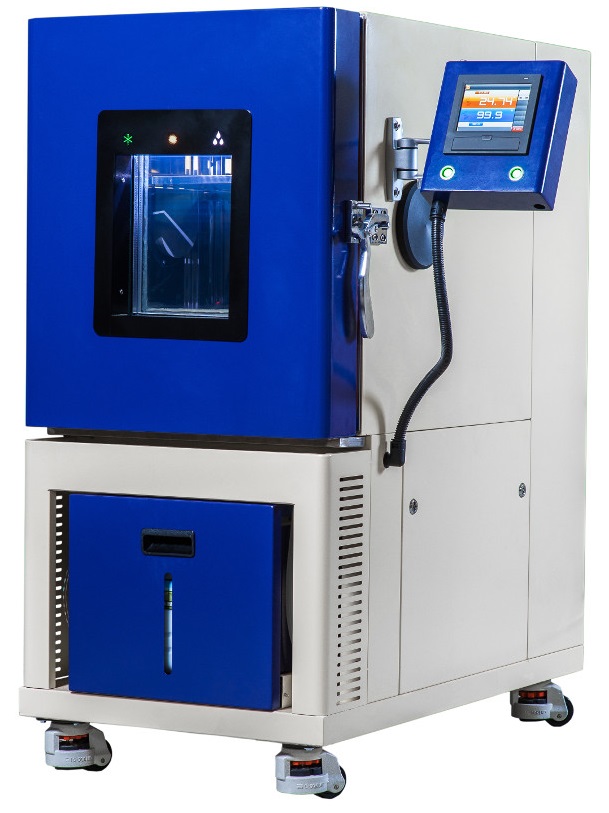
(image is representative, not actual)
Endurance and Environmental automated test system for electro-mechanical sub-system
Automating tests that run for weeks at a time
Client – Automotive component supplier
Challenge
Our client was already doing validation, but it was manual, and the client’s customer started requesting faster turnaround of results. Their customer was also requesting data to be sent with the results. Our client chose to automate the validation process to enhance their productivity.
Solution
Viewpoint utilized the (mostly) existing hardware from the manual tester and developed software to automate the testing. The LabVIEW-based automated test system allows for endurance & environmental validation testing of an electro-mechanical sub-system.
Benefits
- Automates tests that run for weeks at a time
- Logs errors during the test (e.g., for continuous monitoring tests, logging the number of instances of when a UUT’s LIN (Local Interconnect Network) response deviates from a static, current draw outside of limits)
- Capable of testing a large variety of product lines
- Logs pertinent data to a database for post-test analysis/inclusion into reports
System Overview
The UUT is an electro-mechanical part that falls under a variety of different product lines. As such, the client had a couple variants of the tester, based on the communication needs of the UUT. A total of more than a dozen testers were deployed. The functionality of the tester evolved over time, specifically modifying software to make the tests faster / decrease cycle time.
| SOFTWARE FUNCTIONS |
|---|
| Extensive diagnostic/manual operation of system for debug of software and electrical connections between the UUT and the test stand/tooling. |
| Product-specific software components to operate unique products. |
| Execute mechanical endurance tests. |
| Execute environmental endurance tests. |
| Database output containing results from every test cycle (either mechanical cycles or time depending on test being run). |
| HARDWARE USED |
|---|
| USB-LIN module |
| USB and PCI CAN Interfaces |
| Analog input card |
| Digital Input card |
| Digital Output card |
| Power Supplies |
| DMMs |
| Switch Matrix |
| INTERFACES / PROTOCOLS |
|---|
| CAN |
| LIN |
| USB |
| GPIB |
Product Validation of Mechanical Subsystem with NI cDAQ
Product Validation of Mechanical Subsystem with NI cDAQ
The updated product validation tester automates long tests, allowing the client to prove more obviously that their part met the specification.
Client – Automotive Component Supplier / Manufacturer
Challenge
The client already had a test system in place, but it was old and was becoming unmaintainable. Increasing demands from the test engineers and the old software architecture not lending itself to clean implementation of these new features (new sequencer capabilities and ECU CAN communication) drove the need for a rewrite of the software application.
Solution
The updated product validation tester supports product validation of the UUT by automating long tests (sometimes a week or more) providing the desired set point control, allowing the client to prove more obviously that their part met the stated specification. Viewpoint developed the software and the client selected the hardware.
Benefits
- Automate long duration tests
- Improved operator UX by making controls and indicators more intuitive to the user as well as providing additional capability within one application.
- Acquire ECU data along with measured UUT data to allow for engineering performance characterization analysis
- Playback utility enables the Test Engineer to quickly view collected data to chart out a path forward for further testing.
- Automate a Design of Experiments matrix of conditions, through new sequencer capabilities, to more quickly arrive at product characterization parameters.
- All collected signals are now housed in one TDMS file instead of multiple files from different applications.
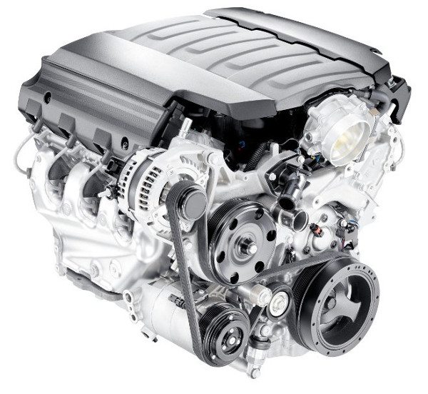
System Overview
The UUT is a complete engine with a focus on one of the mechanical subsystems. Data is collected on over 100 channels, measuring temperature, vibration, strain, RPM, position and pressure. Engine management data (e.g., component location, pressures, engine speed, and status flags) is collected via CAN. The engine speed is set via an analog output, and subsystem setpoints are sent to the ECU via CAN. SCXI still used on some of the old test stands, but is being phased out in favor of cDAQ. The test system software was developed in LabVIEW.
| SOFTWARE FUNCTIONS |
|---|
| Test Sequencing |
| Data Visualization |
| Data Collection |
| Setpoint Control |
| HARDWARE USED |
|---|
| NI cDAQ |
| NI C Series Digital input module |
| NI C Series Digital output module |
| NI C Series Digital input/output module |
| NI C Series analog output module |
| NI C Series temperature input module |
| NI C Series analog input module |
| NI C Series strain/bridge module |
| INTERFACES / PROTOCOLS |
|---|
| Ethernet (TCP) |
| CAN |
LabVIEW-based Data Logger for Product Validation of Commercial Equipment
LabVIEW-based Data Logger for Product Validation of Commercial Equipment
Synchronizing data from multiple data logging instruments
Client – Manufacturer of commercial equipment
Challenge
The client already had a method in place to log data needed for validation testing. However, this data was acquired from multiple independent data logging applications. They needed something to aggregate the data and align/synchronize the data across multiple instruments.
Solution
Viewpoint developed a LabVIEW-based product validation solution that continued to utilize the existing data logging hardware, but uses software to aggregate & synchronize the data from multiple sources. This simplifies post-processing.
Benefits
- Synchronized & aggregated data from multiple instruments
- Ability to add capability for new instruments later on
- Real time graphing of all channels
- Channel averaging across multiple instruments
- Ability to save data acquisition configurations for future use
- Faster channel configuration than current data logging applications
System Overview
The data logging software unifies the collection of data for a particular validation test. The software configures each instrument, kicks them off, logs the data to a TDMS file, and also graphs data and displays real-time values.
| SOFTWARE FUNCTIONS |
|---|
| Instrument configuration |
| GUI |
| Data Acquisition |
| Data Synchronization |
| Data Logging |
| Multi-channel averaging |
| HARDWARE USED |
|---|
| Keysight Data Logger |
| Fluke Data Acquisition DMM |
| INTERFACES / PROTOCOLS |
|---|
| RS-232 |
| USB |
| Ethernet |
Online Monitoring of Industrial Equipment using NI CompactRIO
Online Monitoring of Industrial Equipment using NI CompactRIO
Improving Maintenance of expensive industrial equipment
Client – Large Industrial Equipment Manufacturer
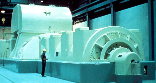
Challenge
The maintenance of the equipment was not always done at the prescribed intervals because the cost of shutting down the plant is significant. This sometimes resulted in an equipment failure. This particular application is for equipment/machinery in the energy/power industry (a generator).
Solution
The online monitoring system monitors a particular parameter of interest to send warnings and alarms to the control room so that the operators know when maintenance needs to be performed on the particular part of interest. This system has been installed in multiple plants.
Benefits
- Enables condition-influenced maintenance intervals vs periodic intervals
- Reduces probability of catastrophic failure by providing warning indicator
System Overview
The system monitors the generator collector health. NI-based data acquisition hardware acquires the signal of interest, logs the raw data, processes the parameter of interest, and triggers/sends warnings and alarms to the control room. LabVIEW FPGA was used for analog and digital IO and a sensor check. LabVIEW Real Time was used for the calculation, data logging, serving data to the HMI and alarm/warning checking.
| SOFTWARE FUNCTIONS |
|---|
| Touchscreen GUI for data/alarm display and system configuration |
| Data logging |
| Signal processing and alarming |
| HARDWARE USED (selected by customer) |
|---|
| NI cRIO |
| NI Touch Panel Computer |
| Multiple NI C Series Modules |
| INTERFACES / PROTOCOLS |
|---|
| TCP/IP |
*- images are representative, not actual
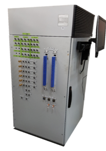
Endurance Testing using NI PXI
Endurance Testing using NI PXI
An automation test stand permits faster validation, unattended test, an increase in throughput, and can free up resources for other tasks during the weeks long endurance test.
Client – A manufacturer of aircraft components in the mil-aero industry
Challenge
New product development drove the need for a new aerospace endurance test stand for product validation. The old systems were not designed to test the newly designed part (aircraft actuators), and the company didn’t have the time or resources to reconfigure existing systems to perform the testing required.
Solution
The new PXI-based endurance test stand provides automated electromechanical testing, full data recording, report generation and a diagnostic panel for intelligent debug. Viewpoint selected the NI equipment while the test stands and other components were selected and fabricated by the customer.
Benefits
- This automated aerospace test stand permits faster validation, unattended test, an increase in throughput, and can free up resources for other tasks during the weeks long endurance test.
- Full data recording with a data viewer enables post analysis, which provides the ability to review and analyze raw signals captured during execution. Channel examples are actuator LVDT position, load, current, and encoder actuator position.
- Summary report capability allows the customer to document the amount of testing completed against the full endurance test schedules.
- A manual diagnostic operational panel provides the ability to verify particular DUT functionality or components without running an entire schedule.
- Systems can be paused and restarted to allow for “scheduled maintenance” of the DUT such as inspections, lubrication, etc.
System Overview
The PXI-based aerospace endurance test stand enables data collection, deterministic PID Loop Control, emergency shutdown and a diagnostic panel for manual test and debug operation. The system runs endurance test schedules, that are defined as a recipe for test execution. These schedules, which are customer-defined and DUT-specific, are designed to simulate the actual conditions the DUT would see in real world application as closely as possible. LabVIEW-RT was used for the deterministic looping for Closed Loop Control of Actuator Position and Load Control. LVDT demodulation was performed on a PXI FPGA card programmed with LabVIEW FPGA.
| SOFTWARE FUNCTIONS |
|---|
| GUI |
| Summary Reports |
| Full Data Collection for Real-Time and Post Analysis |
| Deterministic PID Loop Control |
| E-Stop Management |
| Diagnostics Panel for Manual Test and Debug |
| Endurance Test Schedule Execution |
| Hydraulic Control Panel for Source & Load PSI Control |
| HARDWARE USED |
|---|
| Test stand for PXI hardware and cable connectors |
| PXI |
| Various PXI-based data acquisition cards |
| PXI RT controller |
| PXI FPGA card |
| INTERFACES / PROTOCOLS |
|---|
| TCP/IP |
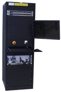
Endurance Tester for Mission-Critical Mechanical Component using NI cRIO
Endurance Tester for Mission-Critical Mechanical Aerospace Component using NI cRIO
Ability to run tests unattended and overnight reduces operator labor and compresses test schedules
Client – Major Aerospace Component Supplier / Manufacturer
Challenge
The client had an older VB & PLC-based aerospace test bench in place already, but it was obsolete. A new endurance test bench needed to be developed to validate prototyped components (in this case, aircraft & aerospace bearings). Many of the prototypes are one-off, so it was important that the test system not destroy the component.
Solution
A new endurance test bench was developed to validate prototyped aerospace components. The test bench can be configured for automatic shutdowns so as not to destroy the component under test in the event of unexpected performance of electro-mechanical subsystem components. The updated endurance tester supports product validation by allowing the product to run under various test conditions (e.g. speed, load, oil flow, temperature) and collecting data for analysis.
Viewpoint developed the software and selected the NI hardware (other hardware was selected by the client).
Benefits
System Overview
The updated cRIO-based endurance tester incorporates configurable profiles, data logging, and automatic shutdown to allow for safer extended validation testing. LabVIEW FPGA and LabVIEW RT were used together to interface with the test hardware sensors and controls. LabVIEW as used create the HMI for the test system.
| SOFTWARE FUNCTIONS |
|---|
| Closed loop control of bearing test oil flow |
| Axial load control |
| Driver for Emerson VFD |
| E-Stop and safety management (shutdowns based on alarm limits) |
| Data collection – temperature, pressure, flow, vibration, frequency |
| Operator/Diagnostic GUI for control of system |
| HARDWARE USED |
|---|
| NI CompactRIO (cRIO) |
| NI C Series Current Input Module |
| NI C Series Voltage Input Module |
| NI C Series Temperature Input Module |
| NI C Series Current Output Module |
| NI C Series Analog Input Module |
| NI C Series Sound and Vibration Input Module |
| NI C Series Digital Module |
| Emerson VFD (Variable Frequency Drive) |
| INTERFACES / PROTOCOLS |
|---|
| TCP/IP |
| TCP Modbus |
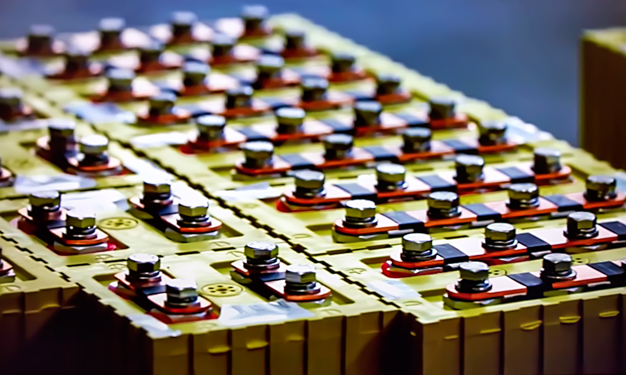
Industrial Automation – Improving Manufacturing Process with a semi-automated welder
Industrial Automation – Improving Manufacturing Process with a semi-automated welder
Automating a battery welder to improve consistency and increase throughput
Client
Industrial manufacturer of battery stacks

Challenge
The previous welding method was all manual, prone to errors and inconsistency. The old system also required the operator be in contact with the module while welding without any safety shielding.
Solution
The welder semi-automates the ultrasonic welding of terminals on a battery module as part of the manufacturing process. It allows for welds to be conducted in the same place for every module, reducing variability and operator errors. This system is also quicker than doing the welds manually.
Benefits
- Increased weld consistency
- Improved operator safety
- Increased welder throughput
System Overview
The system semi-automates the ultrasonic welding of terminals on a battery module. The system consists of an ultrasonic welder, XYZ table, and safety interlocks. The table moves the battery module to the correct welding position. Once in position, the Z portion of the table lowers the welder to the correct welding height. The application sends the signal to the welder to conduct the weld. Weld data is saved to a file from the welder Ethernet interface for later analysis. Viewpoint provided the software for this system, while the client provided the hardware for us to interface with.
Considerable attention was paid to addressing faults in the production process to avoid damage to the operator and the battery module during the welding process, due to the high current output available from the battery module.
| SOFTWARE FUNCTIONS |
|---|
| Welding routing configuration |
| Operator GUI |
| Maintenance mode |
| Interface to welder |
| Interface to table & controller |
| Interface to E-Stop & interlocks |
| INTERFACES / PROTOCOLS |
|---|
| RS-485 |
| Ethernet |
| 24V Digital IO |
How to select a LabVIEW consultant
Maybe you’re LabVIEW programmer quit or retired, or maybe you’ve got some internal capabilities but need some additional support because everyone’s too busy. From hourly rates to a range of skills, there are several factors to consider. We’ll help you weigh each one. See How to Select a LabView Consultant.
LabVIEW developers: local vs remote
Headquartered in Rochester NY, we help customers all over the U.S. See the Pros and Cons of a local vs remote supplier for LabVIEW-based test system development.
3,000+
LabVIEW solutions deliveredGreat for automated measurement & control: manufacturing test, product validation, machine control and condition monitoring.
700+
LabVIEW FPGA systems deliveredGreat for applications requiring seriously deterministic timing, reliable code execution, and multi-channel synchronized processing.
1,000+
LabVIEW RT systems deliveredThe combination of LabVIEW RT and the RTOS on which it runs allows for the creation of applications with bounded jitter and latency.
500+
cRIO-based systems deliveredCombining a cRIO controller with the multitude of C Series modules creates a functional real-time controller in a small footprint.
1,500+
PXI-based solutions deliveredBroad range of off-the-shelf expansion cards & processing horsepower make PXI a formidable choice for many automated test applications.