Custom Automotive Test Equipment Design & Development
Your world is moving fast and it seems the pace is increasing every day. Yet, you need to balance haste with accuracy. Having the right test system helps you achieve that goal.
Our expertise in the automotive industry focuses on test system development, mostly product validation, and bit of manufacturing test.
Fuel consumption ratings, the interest in electric and autonomous vehicles, enhanced safety, and, of course, improved reliability are among some of the most important needs and goals in automotive design and manufacturing.
Design validation and endurance testing test systems need to provide the product and test engineers with the flexibility to assess the performance of a new product design with minimal (or even no) reconfiguration on the test stand, for products in the same family. Plus, with today’s labs and research being global, sharing common test hardware platforms, test applications, and measurement data formats are essential for everyone to be aligned and interactions as frictionless as possible.
For manufacturing, we have intimate experience with end of line test systems that need to be robust and quick. Integration with part handling/detection equipment is essential today, given the level of automation on the production floor.
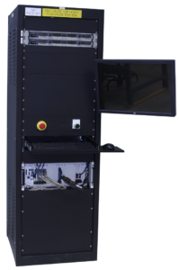
By utilizing PXI, cRIO, and the wide array of measurement and control modules available for these controller platforms, test systems for validation and for manufacturing are based on world-class industry-standard tools. This equipment often needs to be mounted or enclosed in panels/cabinets with all the ancillary support hardware in order to simplify interfacing both the sensors/actuators and the surrounding control equipment, such as PLCs and motion controllers.
How we can help: our capabilities & expertise
Want more proof points? Check out these automotive test case studies:

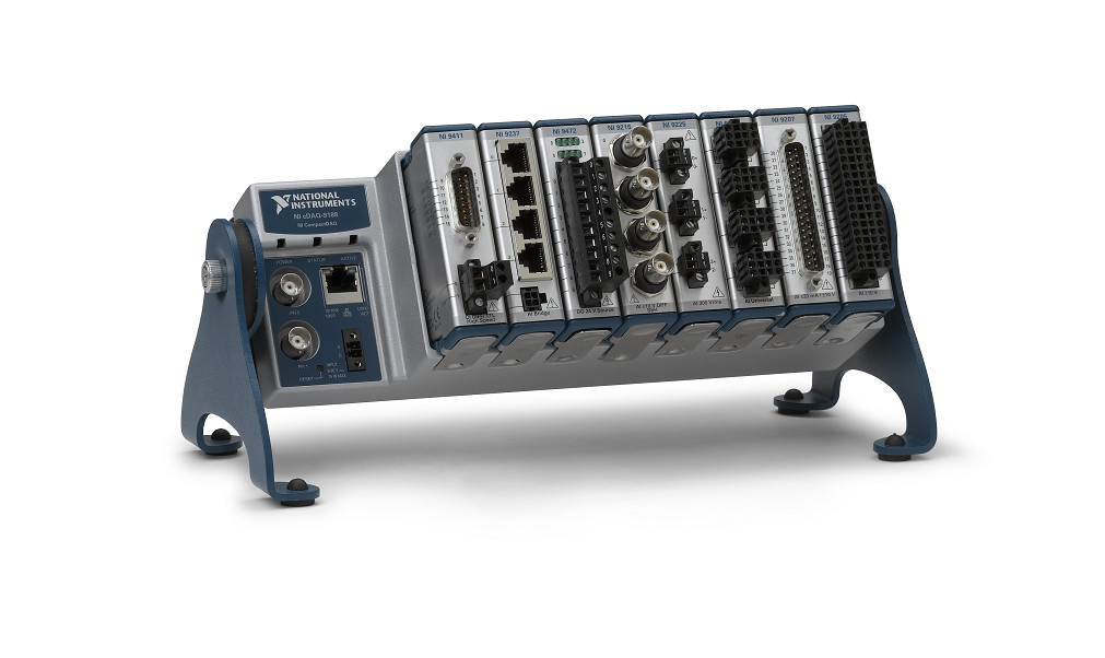
Enhanced Portable Data Acquisition and Data Storage System
Enhanced Portable Data Acquisition and Data Storage System
Using a Real-Time Operating System (RTOS) provides a high level of synchronization and determinism for acquired data.

Client
Tier 1 Automotive Design and Manufacturing Supplier
Challenge
Our client had an existing data acquisition system, used for mechanical product validation testing, that had undergone many updates and patches for over 15 years. These updates and patches, performed by multiple developers, had rendered the software portion of the system somewhat unstable. Furthermore, the system hardware was based on NI SCXI, which was becoming obsolete. These issues prompted our client to migrate to an entirely new system.
New requirements for this upgrade included utilizing a PXI controller running NI Linux Real-Time, a RTOS, executing a LabVIEW RT application. Selection of the replacement NI hardware required knowledgeable engineering to assure compatibility between the selected NI hardware and the legacy SCXI equipment. Part of that compatibility assessment included an understanding of the software application so we could know for certain how the SCXI equipment was used. A blind selection based entirely on hardware specs would have missed nuance, such as the need for synchronized acquisition.
The data acquisition software had to support a variable mix of signal conditioning modules in the PXI chassis. In addition, the data acquired from these signal conditioning modules needed to be synchronized within microseconds.
Solution
Viewpoint leveraged another application, developed for the client a few years prior, to harmonize the user interface and to reduce development effort. Most of the development time focused on support and configuration of the multiple module types and ensuring that the data synchronization functioned as required. The result was an ultra-flexible, portable, high-speed data acquisition software/hardware combination that can be used to acquire time-sensitive, synchronized data across multiple modules in a PXI chassis running a real-time operating system.
Benefits
The upgraded system offers the following features:
- Highly configurable real-time data acquisition hardware/software solution based on LabVIEW RT and PXI hardware. Our client works closely with OEMs to assure compatibility and durability with their products, often going to the OEM’s test cells to collect performance data. The configurability in modules and channels affords the fastest possible setup at the OEM’s site which minimizes time and cost in the test cell.
- Configuration files stored in a SQL database format. Saving channel and module setups in SQL allows the test engineer to locate previous hardware and data acquisition configurations. The usual alternative is a bulk save of an entire system setup rather than using a more granular, and hence, more flexible approach afforded by using the database.
- Immediate test feedback through graphs and analog indicators, used to assure data quality before leaving the test cell.
- Data playback features after the data has been acquired, used for in-depth review of data after leaving the test cell.
- Data acquisition on the RTOS provides assurance that the acquisition will not be interrupted by network or other OS activities, which was occasionally an issue with the prior Windows-based application.
- Synchronization between signal conditioning modules ensures time-critical data taken on separate modules can be compared and analyzed.
System Overview
The system consisted of custom LabVIEW RT software intended to run on an engineer’s laptop and the PXI real-time controller and a PXI chassis populated with a flexible assortment of NI signal conditioning modules (provided by the client).
The software used an object-oriented Actor-based architecture, which facilitates adding new signal conditioning modules and flexible communications between the host PC and the real-time controller.
| SOFTWARE FUNCTIONS |
|---|
| DAQ Task Configuration |
| Event-Based DAQ Trigger |
| Data Synchronization |
| Real-Time Data Visualization |
| Data File Playback Utility |
| Datalogging to TDMS File |
| HARDWARE USED |
|---|
| PXIe Chassis (4,9 or 18-Slot) |
| PXI Real-Time Controller |
| PXI Multifunction I/O Module |
| PXI Digital I/O Module |
| PXI Counter/Timer Module |
| PXI Thermocouple Module |
| PXI DSA Module |
| PXI LVDT Module |
| PXI High-Speed Bridge Module |
| PXI Voltage Input Module |
NI FlexRIO enables Device Evaluation & Characterization for high-data-rate sub-system
NI FlexRIO enables Device Evaluation & Characterization for high-data-rate sub-system
100s of man-hours saved in capturing the data.
Client – Automotive Manufacturer
Challenge
New product development drove the need for validation of a new sub-system (a RADAR sensor ) for use in a next-gen system in an automobile. They needed a way to evaluate and characterize the performance of the component under various conditions that were not defined in the UUTs specs. They wanted to use as much COTS hardware as possible for this first run testing because of the expense of a custom test solution and the timeline.
Solution
The NI FlexRIO-based product validation system utilizes COTS hardware, along with some Viewpoint-developed custom software to allow for evaluation and characterization of the UUT.
Benefits
- The utilization of COTs (vs a custom-built FPGA board) test hardware.
- 100s of man-hours saved in capturing the data.
- Allowed customer to manipulate captured data within the LabVIEW environment for more efficient testing, making changes on the fly.
- Error Checking done at the FPGA Level allows for guaranteed valid transfers
- Packet Decode completed at FPGA Level allows for real-time de-packetization for use in storing only payload data.
- All Data captured with TDMS Files for use in over layering different scenarios.
- Scalable to add additional serial data channels allowing for more than one sensor to be captured with a single FlexRIO card.
System Overview
NI’s FlexRIO with NI’s LVDS FAM was used. The NI flying lead cable was utilized initially to connect to the UUT. On the software side custom VHDL was created to handle the 8b/10b serial stream data and clock recovery. The VHDL interfaced to LabVIEW FPGA which was utilized to stream the data to disk on the PXI-based system.
| SOFTWARE FUNCTIONS |
|---|
| Custom FAM VHDL and LabVIEW FPGA interface Development |
| Aurora 8b/10b de-serialization and clock recovery |
| LVDS Buffering |
| Clock to Internal LabVIEW FPGA Clock |
| FIFOs for clock domain crossing and DMA |
| High Speed data streaming to Disk |
| LabVIEW RT for example Interface to FPGA |
| GUI |
| HARDWARE USED |
|---|
| NI FlexRIO |
| NI FlexRIO FAM – LVDS |
| NI LVDS to Flying lead cable |
| NI PXI Chassis and Controller |
| INTERFACES / PROTOCOLS |
|---|
| Aurora 8b/10b |
| TCP/IP |
Manufacturing Inspection System Uses Machine Vision to verify assembly and labeling
Manufacturing Inspection System Uses Machine Vision to verify assembly and labeling
Reducing human error with automated inspection
Client – Automotive Component Manufacturer
Challenge
Our client already had an end-of-line tester in place. However, preventing incorrect product shipments drove them to add machine vision capabilities to verify that the part being packed is of the correct physical configuration and that the part was labeled correctly. They also wanted a more automated way to track which serial numbers were being shipped.
Solution
Viewpoint enhanced the existing end-of-line tester by adding machine vision capabilities to verify correct part assembly and part labeling. This capability also allowed for automated tracking of which parts went into which shipping container.
Benefits
- Automated part assembly verification to reduce human error from manual visual inspection
- Automated label verification to reduce the chance of shipping the wrong product
System Overview
The enhanced system added machine vision-based capabilities to an existing end-of-line manufacturing test system. New hardware (cameras, lighting, fixture) was selected and integrated by the client. Viewpoint developed the image analysis routines using the Cognex In-Sight software. These routines were then downloaded and controlled using LabVIEW software developed by Viewpoint. In addition, the LabVIEW GUI contained the image acquired by the camera and the results of the image analysis. The tester can inspect four different part types.
The software essentially performs the following functions:
- Look up the expected characteristics of the part being inspected.
- Populate the on-camera In-Sight “spreadsheet” with configuration information used in the image analysis/inspection.
- Trigger the image capture and read results from the on-camera spreadsheet.
- Use the on-camera image analysis to check a critical angle of the part as the part is set in the nest fixture.
- Check the information laser etched on the part and compare the results with what should be on the part (relative to the barcode read in for the lot and the 2D barcode on the part) using the OCR/OCV capabilities of the camera.
- Perform other physical part characterization image analyses to verify the part was correctly labeled & assembled.
| SOFTWARE FUNCTIONS |
|---|
| Look up expected part characteristics |
| Trigger image capture |
| Read results of on-camera image analysis |
| Display image taken by camera and show if test passed or failed |
| Monitor contiguous part failures & initiate shutdown |
| Log vision test failures to database |
| HARDWARE USED |
|---|
| Existing end-of-line tester |
| Test Fixture |
| (qty 2) Cognex camera |
| Lighting for camera |
| INTERFACES / PROTOCOLS |
|---|
| TCP/IP |
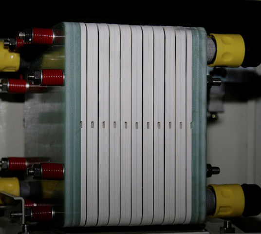
Endurance and Environmental automated test system for electro-mechanical sub-system
(image is representative, not actual)
Endurance and Environmental automated test system for electro-mechanical sub-system
Automating tests that run for weeks at a time
Client – Automotive component supplier
Challenge
Our client was already doing validation, but it was manual, and the client’s customer started requesting faster turnaround of results. Their customer was also requesting data to be sent with the results. Our client chose to automate the validation process to enhance their productivity.
Solution
Viewpoint utilized the (mostly) existing hardware from the manual tester and developed software to automate the testing. The LabVIEW-based automated test system allows for endurance & environmental validation testing of an electro-mechanical sub-system.
Benefits
- Automates tests that run for weeks at a time
- Logs errors during the test (e.g., for continuous monitoring tests, logging the number of instances of when a UUT’s LIN (Local Interconnect Network) response deviates from a static, current draw outside of limits)
- Capable of testing a large variety of product lines
- Logs pertinent data to a database for post-test analysis/inclusion into reports
System Overview
The UUT is an electro-mechanical part that falls under a variety of different product lines. As such, the client had a couple variants of the tester, based on the communication needs of the UUT. A total of more than a dozen testers were deployed. The functionality of the tester evolved over time, specifically modifying software to make the tests faster / decrease cycle time.
| SOFTWARE FUNCTIONS |
|---|
| Extensive diagnostic/manual operation of system for debug of software and electrical connections between the UUT and the test stand/tooling. |
| Product-specific software components to operate unique products. |
| Execute mechanical endurance tests. |
| Execute environmental endurance tests. |
| Database output containing results from every test cycle (either mechanical cycles or time depending on test being run). |
| HARDWARE USED |
|---|
| USB-LIN module |
| USB and PCI CAN Interfaces |
| Analog input card |
| Digital Input card |
| Digital Output card |
| Power Supplies |
| DMMs |
| Switch Matrix |
| INTERFACES / PROTOCOLS |
|---|
| CAN |
| LIN |
| USB |
| GPIB |
Product Validation of Mechanical Subsystem with NI cDAQ
Product Validation of Mechanical Subsystem with NI cDAQ
The updated product validation tester automates long tests, allowing the client to prove more obviously that their part met the specification.
Client – Automotive Component Supplier / Manufacturer
Challenge
The client already had a test system in place, but it was old and was becoming unmaintainable. Increasing demands from the test engineers and the old software architecture not lending itself to clean implementation of these new features (new sequencer capabilities and ECU CAN communication) drove the need for a rewrite of the software application.
Solution
The updated product validation tester supports product validation of the UUT by automating long tests (sometimes a week or more) providing the desired set point control, allowing the client to prove more obviously that their part met the stated specification. Viewpoint developed the software and the client selected the hardware.
Benefits
- Automate long duration tests
- Improved operator UX by making controls and indicators more intuitive to the user as well as providing additional capability within one application.
- Acquire ECU data along with measured UUT data to allow for engineering performance characterization analysis
- Playback utility enables the Test Engineer to quickly view collected data to chart out a path forward for further testing.
- Automate a Design of Experiments matrix of conditions, through new sequencer capabilities, to more quickly arrive at product characterization parameters.
- All collected signals are now housed in one TDMS file instead of multiple files from different applications.
System Overview
The UUT is a complete engine with a focus on one of the mechanical subsystems. Data is collected on over 100 channels, measuring temperature, vibration, strain, RPM, position and pressure. Engine management data (e.g., component location, pressures, engine speed, and status flags) is collected via CAN. The engine speed is set via an analog output, and subsystem setpoints are sent to the ECU via CAN. SCXI still used on some of the old test stands, but is being phased out in favor of cDAQ. The test system software was developed in LabVIEW.
| SOFTWARE FUNCTIONS |
|---|
| Test Sequencing |
| Data Visualization |
| Data Collection |
| Setpoint Control |
| HARDWARE USED |
|---|
| NI cDAQ |
| NI C Series Digital input module |
| NI C Series Digital output module |
| NI C Series Digital input/output module |
| NI C Series analog output module |
| NI C Series temperature input module |
| NI C Series analog input module |
| NI C Series strain/bridge module |
| INTERFACES / PROTOCOLS |
|---|
| Ethernet (TCP) |
| CAN |
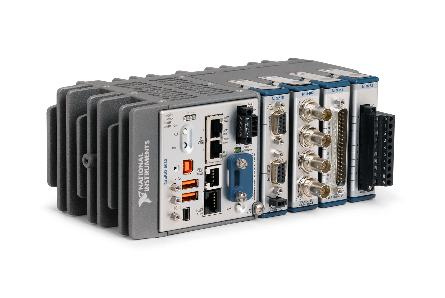
Endurance Tester using NI cRIO
Endurance Tester using NI cRIO
Multiple International Deployments Helps Prove Product Meets Spec.
Each endurance test can run upwards of 6 months.

Client: Major Automotive Component Supplier
Challenge
A new endurance test system was developed to give more precision in the control setpoint. This additional precision enabled potential clients to review the product performance in real-life situations. Each endurance test can run upwards of 6 months.
Solution
The updated endurance tester supports product validation by providing the desired parameter control method, allowing the client to prove more obviously that their part met the stated specification.
Viewpoint developed the software and selected the NI hardware for the first unit. The client is now deploying copies of this system to multiple international manufacturing plants.
Benefits
- Able to prove meeting a particular product specification of interest
- Closed loop parameter control
- Data collection
- Configurable Alarms
- Emergency shutdown functionality
System Overview
The cRIO-based endurance tester provides closed loop control, data collection, and alarming with controlled and emergency shutdown functions. The operator can manually configure a test or load a saved configuration. After a manual operator check to make sure the setup is operating correctly, a successful test will run its full duration and stop on its own.
| SOFTWARE FUNCTIONS |
|---|
| Touch PC interface / GUI |
| Closed loop parameter control |
| Data collection |
| Controlled & emergency shutdown |
| Alarming |
| HARDWARE USED |
|---|
| NI CompactRIO |
| NI analog input cSeries module |
| NI analog output cSeries module |
| NI digital input cSeries module |
| NI digital output cSeries module |
| INTERFACES / PROTOCOLS |
|---|
| TCP |
Creating an N-Up Tester to handle increased production volume demands
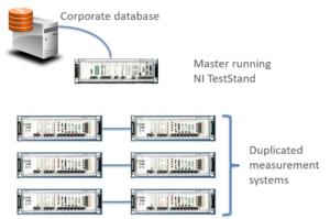
Creating an N-Up Tester to handle increased production volume demands
Enhanced throughput offers ROI payback period of less than 1 year
Client
Automotive Components Supplier / Manufacturer
Challenge
The company makes automotive components in very large volume, several part models each at more than 1 million per year.
The client’s primary concern was conserving floor space. They were completely out of spare manufacturing space.
Solution
Viewpoint created an N-up NI PXI-based Manufacturing Test System. In this case, N=6 because analysis showed that a 6-up electronic part tester allowed the test operator to cover the test time with the load/unload time.
At the high volumes needed, the client needed to parallelize as much as possible. The cost of 6 sets of test equipment and device sockets was less important than speed. Using the equation:
ProfitPerUnit x NumberAdditionalPartsPerYearAfterParallelizing > CostOfTestEquipment,
being able to completely parallelize made the number of extra units per year large enough that the payback time for completely duplicating the measurement instrumentation for each UUT socket was less than about 1 year.
Benefits
- Paid for itself in less than 1 year by the enhanced throughput.
- This approach consumed about 20% the floor space that would have been used for duplicating the test system 5 more times (for a total of 6 testers)
System Overview
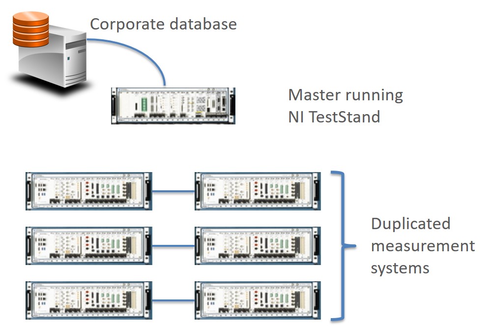
Viewpoint developed an NI TestStand application that ran 6 instances of the test sequence independently of each other utilizing the duplicated PXI-based test equipment. The common parts of the overall master sequence were:
- Startup check for the entire test stand
- Shutdown of the entire test stand
- Archiving the test results into the database
Part handling was managed by a PLC and robot which delivered the parts from a tray into the UUT sockets. Digital bits were used for signaling the test sequence which parts were present in their sockets and ready to test.
| SOFTWARE FUNCTIONS |
|---|
| Test System GUI |
| Test sequencer |
| Startup checker |
| Test Results Archiver |
Designing an Automated Fuel Cell Validation Test Stand
Designing an Automated Fuel Cell Validation Test Stand
Verifying a New Fuel Cell Design Through Automated Operation
Client: A major automotive manufacturer
Problem Scope
Micro Instrument, an automation vendor that builds product validation and test stands, has extensive experience with programmable logic controllers (PLCs) and stand-alone controllers for controlling repetitive motion, safeties, and other “environmental” parameters such as pressure and temperature. The company typically uses PLCs to reliably deliver discrete I/O control and standard PID loop control.
However, Micro Instrument’s customer, a major automotive company, was interested in investigating fuel cells as a power source and they needed to run these fuel cells under a wide range of conditions for extended durations, for both design validation testing and durability testing purposes. These fuel cells required more advanced control algorithms than could be provided with a simple PID. A more powerful controller was needed.
Challenge
The customer knew they needed control loops that predicted system response so we could eliminate overshoot and/or achieve a faster approach to a setpoint. But, because the customer did not know in advance exactly what such “smart” controls would entail, it was beneficial to have the full power of LabVIEW to develop such controls. Providing this functionality with a PLC would be cumbersome, if not impossible.
The customer had some Compact FieldPoint which they wanted to use for this project, so we needed to ensure that this equipment would be sufficient to deliver the required control performance and tolerances. Also, the system needed to conduct PID control in two forms – PWM and continuous control. Importantly, this Fieldpoint hardware had a real-time controller running LabVIEW Real-Time.
Solution
The test system we developed included a 19″ rack test stand populated with fuel piping and control, power supplies, harnessing, data acquisition and control hardware. This hardware was a NI Compact FieldPoint controller, chassis, and modules. The Compact FieldPoint controller was programmed with LabVIEW Real-Time to meet the customer’s system control demands. For example, to predict system response, we programmed the Compact FieldPoint to run control loops that were aware of imminent system-state changes and changed their control schemes accordingly.
As with most validation test systems, we needed to monitor conditions for safety. New product designs are often operated near the edges of safe operation in order for the designer to understand how the product performs in extreme conditions. For this fuel cell application, destructive over-heating and over-pressure could occur. Both digital and analog signals were watched in real-time to assure operation within reasonable bounds and allow a safe shutdown if the fuel cell ran into out-of-bound conditions.
The application used the following independent parallel loops:
- Seven for PWM-based temperatures control
- Two for continuous pressure monitoring
- Four for solenoid and sensor monitoring and control
- 15 safety loops
Data collected during the validation tests were saved to a local PC for later performance analysis and anomaly detection.
The combination of Compact FieldPoint with LabVIEW Real-Time enabled the customer to run the required custom control algorithms and it surpassed the capabilities offered by standard PLCs.