
How we used agentic AI to build a test system application – a real-time data acquisition, processing and control loop in C++
Understanding the benefits and risks of using generative AI for test system applications by recreating Viewpoint’s Pulsar RT architecture.
The motivation
Artificial intelligence (AI) has become powerful enough to assist in designing and coding substantial, production-grade applications. We decided to explore these capabilities to learn more about what current Large Language Models (LLMs) and agentic AI coding platforms can achieve to assist in the development of automated test systems that test manufactured products.
We started by asking: “What if we build something similar to what we’ve done before?”. By replicating an existing architecture, we knew the requirements precisely, allowing us to evaluate the generated code without ambiguity.
Rebuilding a familiar system also allowed us to observe how AI approaches problem-solving compared to traditional engineering design and development methods.
We chose to rebuild one of our widely used architectures which we deploy in many test applications, especially in aerospace. This architecture is called Pulsar RT. We use Pulsar as part of our test systems to verify proper functionality for the Device Under Test (DUT). Typical DUTs where it makes sense to use Pulsar are typically electromechanical, such as actuators, motors, pumps, and valves.
Furthermore, because we work extensively with LabVIEW and LabVIEW RT, we wanted to see how the Pulsar architecture could be implemented in C++ across microprocessor (µP) platforms and alternative data acquisition hardware not supported by LabVIEW.
What we learned
The primary takeaway for this project is that agentic IDEs are amazing! We worked with Gemini and Antigravity for this project, but we suspect other IDEs and LLMs would produce similar results.
Without being an expert in C++ and Linux configurations, we were able to create a hardware-agnostic, real-time loop for data acquisition, processing, and control that maintains dropout-free communications with a host PC. And, for all but the least powerful µP, the Pulsar loop can run at 1 kHz.
We also leveraged Gemini / Antigravity to create a Python app for the Host PC with a UO based on PySide. Again, the agentic AI leveraged the python code base on the web to create an app which would have taken us days or maybe weeks to learn PySide sufficiently to build a GUI for the Host PC down to less than 1 day.
Some lessons we learned about being effective with Agentic AI:
Experience with AI tools is necessary
We needed some time using Gemini and the Antigravity IDE to understand their capabilities.
Verification is needed
The output code looks very complete at first glance but testing showed clear errors (e.g. timing of the Pulsar loop). To validate the code, we performed:
- Hardware testing that included measuring cycle timing, jitter, and channel values
- Software testing that included long-term operational reliability, proper analog I/O scaling, scanning for gRPC dropouts.
Clear prompts are needed
Feeding specific and detailed instructions and requirements is critical to success.
We found that having a human knowledgeable of software development methodologies is needed to put “guardrails” on the design and details output by the Agentic AI.
Agentic AI cannot solve all problems
Humans still add value.
We found that LLMs can easily “go down a rabbit hole” if not monitored by a human who can determine that the LLM is going in a wrong or ineffective direction.
Understanding how to use OOP, data structures, and unit testing enables people to write better prompts and to recognize when the AI is “misbehaving”. For example, solutions may require a new direction, such as adding or changing the hardware, or simplifying the design to achieve certain requirements. Agentic AI is not that creative … yet.
Using generative AI successfully requires regular testing of the generated code and iterative troubleshooting with the AI agent.
 John Snyder, Partner, Viewpoint Systems
The following sections explain the details of our experiment.
The Pulsar RT rebuild plan
The real-time loop
We wanted to duplicate the functionality of the Pulsar real-time loop. This loop continuously cycles through:
- Input: Read measurements from the DUT and any other relevant hardware.
- Process: Execute algorithms using the measurements and configuration parameters.
- Output: Send updated control values to the DUT and test stand hardware.
A memory block, which we call a Data Vector, is used to store measured and computed values, which are then extracted and written to the hardware at the end of the loop cycle. This Data Vector is also shared between the Host PC and the RT controller so the host can monitor and affect the activity on the RT controller.
Here’s a diagram showing the elements of the RT loop and the Data Vector:
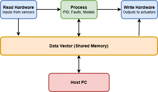
Figure 1 – Pulsar real-time loop diagram
Depending on the type of DUT, such as aerospace actuators, motors, and other electromechanical devices, the loop time can be as little as 1 ms. And, we want the jitter in this periodic timing to be a small fraction of the loop period, say less than 1/10.
Agnostic architecture to support different controllers
Pulsar was originally written in LabVIEW and targeted NI real-time hardware, such as CompactRIO. To enable the Pulsar architecture to run on both NI and other hardware, we needed to add layers to the software to make it hardware-agnostic so it could run on several microprocessor-based data acquisition (µP-based DAQ) systems.
Specifically, we looked to target platforms such as Raspberry Pi and Arduino. Some of our clients are looking at these devices. Of course, we’d also like to run the agnostic code on the NI CompactRIO, since we use the cRIO almost exclusively in our test systems.
Targeting these other µP-based systems requires modular code with a hardware abstraction layer (HAL) in a language that each controller can support. We chose C++ since it’s widely supported. We could use LabVIEW on the host test PC.
Another reason we chose C++ is that we knew that LLMs have been trained on the huge library of C++ code on the web, so we had some confidence that we could be successful with using C++ for this project. (Remember that the motivation for this project was to gain experience coding a useful tool with an LLM and its associated Agentic AI coding environment.)
Also, we had to consider a widely accepted method to communicate between the host PC and the µP. We considered options like low-level Ethernet, REST, high-level OPC, gRPC, and others. We chose gRPC mainly because it’s designed for fast and low-latency and bi-directional streaming, perfect for this RT µP looping. Plus, it’s supported in many languages, including C++.
Using agentic AI to code the application
Using an agentic AI tool entails giving it a clear description of the design goals and functionality of the application. In other words, we needed to create a list of architecture design and functional requirements for our application to meet. The more clear and logical this set of requirements, the fewer iterations we’d need with the agentic IDE.
Rough out the overall architecture
Since we’re intimately familiar with the Pulsar RT architecture that we created in LabVIEW, building out the requirements to feed the LLM was hugely accelerated by the knowledge we had gained during the previous ~15 years of usage and updates of the original application.
To achieve the goal of porting Pulsar to other µP platforms, we needed to add the HAL and some other capabilities not included in the LabVIEW version, since that version targeted only the cRIO platform. Specifically, we wanted:
- Hardware abstraction: Implement a HAL to modularize and make the physical analog and digital I/O independent of the µP platform.
- Deterministic timing: Abstract the configuration of the real-time operations to utilize µP-specific hardware and/or OS functionality to achieve low-jitter, fast loop timing for both non-NI and NI platforms.
- Modernized Comms: Replace the raw Ethernet communication method used in LabVIEW with gRPC streaming.
Of course, there were additional details to be defined and refined during the development, but feeding these requirements to the LLM gave a solid frame on which to hang those details.
Let’s give a summary of the agentic AI platform that we used and some details of how we described the work breakdown structure.
Antigravity agentic AI development platform
Several agentic AI environments exist. At the time of this project, we could choose from Antigravity, Claude Code, Codex, and Cursor.
We chose Antigravity.
We started off by describing the architecture and requirements listed above with some additional details like:
- the need to run on Linux in real-time,
- using C++ functions,
- and configuring the hardware to minimize jitter in the loop.
Then we broke down the problem into two major parts:
- Architecture design for the Pulsar RT loop, as shown in Figure 1.
- Methods and code to reduce loop jitter to a sub-ms level.
Next, we review some details of these two major architectural parts.
Implementing Pulsar’s real-time loop
As the heart of the Pulsar RT architecture, the real-time loop requirements were fed into the Agentic AI with a precise prompt. This prompt covered a description of the diagram in Figure 1 with additional guidelines about flow of data between the various parts (e.g., threads) of the RT architecture:
- Conflict-Free Shared Data Structures: To prevent read/write collisions between threads, we avoided any blocking mutexes. Instead, we coordinated access to shared data using lock-free data structures.
- Sequential Loop Execution: The RT thread executes deterministically on each hardware interrupt tick: it polls updates from the host, reads and scales physical inputs, calculates values, writes physical outputs, and queues status telemetry for the host.
- Asynchronous Host Control: Configuration values (such as waveform parameters and control tuning values) are sent asynchronously by the host via gRPC and safely queued for the real-time loop.
- Decoupled High-Speed Streaming: Input data is read from physical inputs, scaled, and placed into the data vector. A background gRPC thread periodically pulls this vector, packages it, and streams chunks to the host at some configured multiple of the RT loop period.
We leveraged the NI myRIO as the first target, and then the Raspberry Pi as the second target.
See the Appendix for some initial prompts targeting the myRio and the Raspberry Pi.
The agentic AI generated about 20,000 lines of code, mainly in C++ source and header files and a Python app for the host PC.
We were surprised how little prompting was needed to produce some very functional code. We wondered if this type of application is common enough that the LLM identified code previously created for a similar application.
Reducing loop jitter
One of the most important aspects of the Pulsar application is the need for a solid time-critical loop that also has low timing jitter.
Low jitter is important because the loop might be executing an HIL model, PID control, safety checks, or other functionality that expects the delta-time between successive loop executions to be consistent. For example, digital HIL models approximate continuous integrals and differentials based on a fixed delta-t. If delta-t is inconsistent, the model output will contain unexpected numerical error since delta-t will sometimes be too small and sometimes too large. These errors appear as noise in the physical output.
In achieving low jitter, the Agentic AI was surprisingly helpful. We didn’t have to learn about all the intricacies of each µP and its OS. Instead, we defined our timing and latency requirements and the LLM output code with appropriate C++ function calls and settings to configure the hardware and OS.
For example, the Agentic AI output contained details like:
- Memory locks: memory blocks for the gRPC buffer were locked in place to eliminate memory thrashing.
- Data alignment: data elements were tied to 8-byte boundaries for consistent timing with memory R/W calls.
- Pre-allocation: memory blocks were pre-allocated before the loop started.
- Assigning cores: certain parts of the code, such as the RT loop code, were assigned to specific cores to isolate execution from standard OS processes.
- Priority levels: a high-priority OS preemption level was given to the loop code for RT scheduling purposes.
- Hardware timing: if the µP allowed it, hardware-based synchronization was used based on FPGA or hardware interrupts rather than software “sleep” functionality.
If we had to dig through µP manuals, online forums, and OS operational details to learn and understand how to implement these details, we would have consumed days, possibly even weeks, of our time. Instead, we were given code that executed within a day of initial specifications!
To be realistic, the code was only mostly functional, as we learned when we started testing the application.
Testing
The primary verification tool was an oscilloscope to check the loop timing and jitter.
When we put code in the loop to toggle a digital output line, we saw unacceptable timing errors and jitter in the scope trace in our initial attempt.
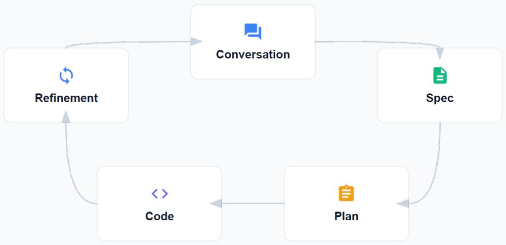
The Agentic AI was then fed descriptions of our observations coupled with expectations (reminders?) on how the code needed to work. We had to go through a few iterations of this process before the code finally performed the way we wanted. Below is a flowchart illustrating the process we used for continuous improvement.
It was interesting to us that the fixes made by agentic AI during these iterations were sometimes subtle and “down in the weeds”. That these fixes spanned such a broad range of responses caused our responses to span from “wow, that was a bit of an awesomely unexpected fix” to “wow, we are glad we didn’t have to scrape together all that detail but the code is about what we’d expect”.
We also needed to verify that the gRPC comms worked reliably with no dropped data packets. That check was done by filling the shared memory buffer with known data both to and from the host PC to look for unexpected values. We ran this setup for an hour or so, and detected no dropouts.
With the RT loop timing in good shape and the comms working between the host PC and the RT layer, we had a functioning application built on an architecture that was modular and designed to be agnostic of the hardware it ran on. Additional µP targets could be supported by modifying the particularities of the I/O and OS configurations for that specific µP.
And a caution
Data privacy should be a concern for any test group. Chats with agentic IDEs and the LLMs inside them save all the prompts and data fed to them to provide context and history of the conversation. Without some caution, you might include in the prompts some specifications of a proprietary product or process.
If a project you are working on is covered by an NDA, ITAR, CMMC, or any other privacy or security requirements, don’t use LLMs without understanding how they treat data you give them.
Some platforms offer self-hosting to keep data in-house or provide cloud configurations that reside only in the US, and delete any data from the conversation after the session is over. Those protections may cause tradeoffs in terms of costs, performance, and newness of the LLM model version.
Next steps
The usefulness is clear: test engineers can increase their test system development efficiency by leveraging agentic AI.
Coding is the obvious use-case. If you develop with text-based languages, the Agentic AI tools and their LLMs available today (2026) will create an immediate benefit.
If you develop with LabVIEW, continue to pay attention to Nigel, as its capabilities will grow with time and it has some unique advantages over other LLMs since it can interface with all the LabVIEW+ Suite platforms, such as TestStand, VeriStand, and FlexLogger. NI also recognizes that companies doing test are concerned about data privacy and, unlike the typical LLM, Nigel has a good story to tell about protecting data.
If you have not used agentic AI yet, remember that experienced test engineers are an essential part of success. While agentic AI can significantly accelerate software development and improve productivity, achieving the best results still requires engineers who understand how to design, integrate, and validate complete test systems. This expertise is even more imperative when hardware, instrumentation, and real-world system behavior are involved.
Engineers provide the creativity, judgment, and systems-level thinking needed to solve complex integration challenges, minimize schedule risk, and keep projects within budget. The most effective solutions come from leveraging the strengths of both AI and experienced engineering teams.
Appendix
Initial prompt for the myRIO
This was the very first prompt that started the experiment with the myRIO:
I have an NI myRIO attached at 172.22.11.2. The operating system on the myRIO is Linux 4.14.146-rt67 #1 SMP PREEMPT RT. In C++ create a program that runs a real time 1 kHz loop. The loop will toggle the digital ouput associated with LED 0 through 3. The NI generated C code to interface with the LEDs through the FPGA are in the src directory. Toggle the LEDs with a 50% duty cylce at the following rates: LED0: 1 Hz, LED1: 2 Hz, LED2: 4 Hx, LED3: 8 Hz. Set all LEDs to off when the program closes. The cross-compile environment for the myRIO is here: C:\build\18\arm
Initial prompt for the Raspberry Pi
The initial effort on the myRIO was ported to another folder because the code had become too complicated, had outgrown the initial goal (as described above followed by additional prompts), and needed some folder structure in another project directory. Plus, we realized more detail was needed to direct the Agentic AI towards the agnostic RT loop functionality.
The Gemini / Antigravity Agentic AI was then asked to create a project migration prompt to create a new project directory to start working on making the code more modular and hardware agnostic. Here’s the AI-generated prompt for the Agentic AI. It’s interesting how we used AI to prompt AI.
Hello! I am migrating to a new, clean workspace to begin a massive architectural refactor of a C++ Real-Time Control System. Please load the following context into your memory.
### 1. Where We Came From (The Prototype)
In our previous workspace (“myRIO RT Heartbeat”), we successfully built a fully functioning prototype on the NI myRIO. It featured:
* A deterministic 1 kHz FPGA-driven Time-Critical (TC) loop in C++.
* Asynchronous gRPC streaming and configuration using atomic, thread-safe Lock-Free Queues.
* A Python PyQt dashboard and a streaming NI Measurement Plugin for InstrumentStudio.
* Functional modules including Analog Waveform Generators, AI Fault Monitoring (with latching and persistence), and LED diagnostics.
### 2. The New Goal: Hardware Abstraction Architecture
We are abandoning the tightly-coupled myRIO prototype in favor of a universal, hardware-agnostic architecture. This new system must be capable of running identically on NI PXIe RT Linux systems, Raspberry Pis, Beaglebones, or the original myRIO. The core executable must have zero direct knowledge of the underlying hardware.
### 3. Core Architectural Blueprint
We have defined the following architecture in our `requirements_cpp.md` document, utilizing a PLC-style “Process Image” and a Two-Phase Initialization pattern to guarantee blazing-fast pointer access without memory reallocation issues.
#### A. The `IDaq` Interface
An abstract base class that all hardware plugins (e.g., `myRioDaq`, `PxiDaq`, `PiGpioDaq`) will inherit from. It mandates the following lifecycle methods:
* `Initialize()`: Talk to the hardware and reserve memory.
* `LinkMemory()`: Resolve memory handles into permanent raw pointers.
* `ReadInputs()`: Read from physical HW -> Write to Data Vector.
* `WriteOutputs()`: Read from Data Vector -> Write to physical HW.
* `Close()`: Safe hardware shutdown.
#### B. The `DataVector` (Process Image)
A centralized class managing a massive, pre-allocated, contiguous block of memory. This guarantees maximum L1/L2 cache hits during the high-speed loop.
#### C. The Two-Phase Initialization
- **Phase 1 (Sizing):** During `IDaq::Initialize()`, the DAQ module calls `DataVector::AddSection(name, size)`. The DataVector tallies the required bytes and returns an integer **Handle / Offset** (NOT a pointer).
- **Phase 2 (Allocation):** The Main System calls `DataVector::Initialize()`, which formally allocates and locks the `std::vector` or raw buffer in RAM. It will never resize again.
- **Phase 3 (Linking):** The Main System iterates over the DAQs calling `IDaq::LinkMemory(DataVector& dv)`. The DAQ passes its Handle back to `DataVector::GetPointer(handle)` to receive a finalized, permanent raw pointer (e.g., `double*` or `std::span`).
#### D. The Time-Critical (TC) Loop
The system will maintain a collection of instantiated DAQs (e.g., `std::vector<std::unique_ptr<IDaq>>`). Inside the 1 kHz loop, the system blindly iterates over this collection, executing:
- `daq->ReadInputs()` (DAQs use their mapped raw pointers to push physical data into the DataVector).
- *… (Any control logic or fault monitoring processes the DataVector) …*
- `daq->WriteOutputs()` (DAQs use their mapped raw pointers to pull data from the DataVector to the physical hardware).
### 4. Immediate Next Steps
- Scaffold the new CMake project directory structure (e.g., `src/core`, `src/hw`, `src/grpc`).
- Draft the `IDaq.h` and `DataVector.h` header files based on the Two-Phase Initialization pattern.
- Help me port over the reusable assets from the old prototype (Python UI, Measurement Plugin, protobuf definitions, and lock-free queues).
