Industrial Embedded White Papers & Webcasts
Industrial Embedded System Design Services – How much does it cost to prototype?

Industrial Embedded System Design Services – How much will the embedded development cost to prototype the first unit?
Are you developing a new industrial product and want to know what it’ll take to develop the prototype embedded controller?
You’re in luck. This calculator can start to give you a feel for the costs. Note that I said “feel”. That’s because it’s just a rough ballpark estimate. There’s usually additional information that will change the costs that’s not easily captured in a calculator because there’s too many unique scenarios. Reach out to us for more accurate pricing.
This calculator is intended to capture the engineering costs (mostly software development, debug, and integration) to develop the first unit. Here are the major assumptions:
- COTS (off-the-shelf) hardware can be utilized.
- Hardware costs are not included.
- Decent requirements have been created.
Engineering Prototype Cost Calculator – for Industrial Embedded sub-systems that use COTS hardware
If you’re interested in considering Viewpoint for your development, check out our capabilities here, then reach out here. If you’re looking for additional industrial embedded resources, check this out.
LabVIEW Industrial Automation Guide
LabVIEW Industrial Automation Guide
- Use cases
- Gotchas
- How it can help
- How to get help
How it can Help – with use cases
To make sure we’re on the same page when we say “LabVIEW industrial automation”, we’re NOT talking about test system automation using LabVIEW. If you’re interested in that topic, see here.
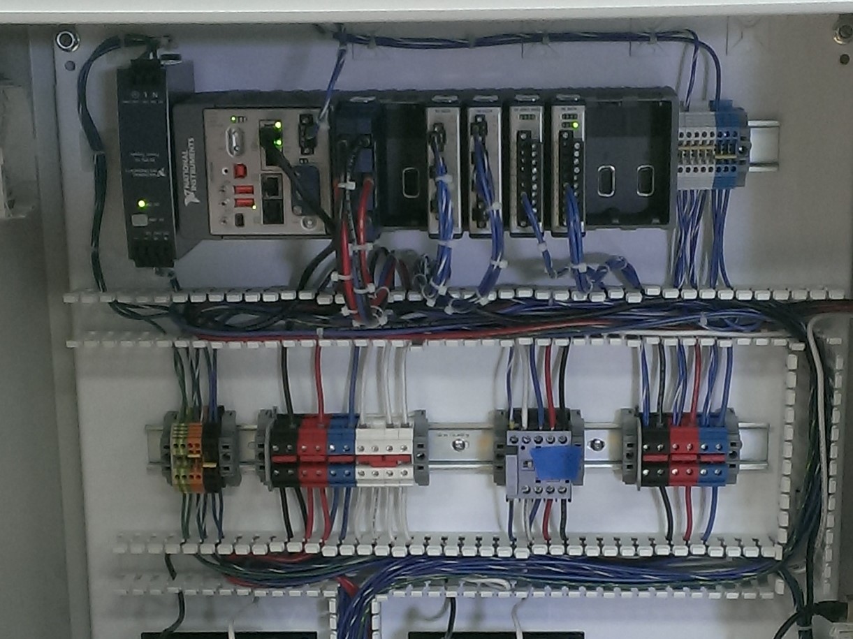
LabVIEW can be used to help with your industrial automation needs divided into two main use cases: (1) machine control and (2) machine monitoring. It can either be embedded as the core brains for an OEM machine or piece of equipment, or bolted on to augment the core capabilities of the equipment.
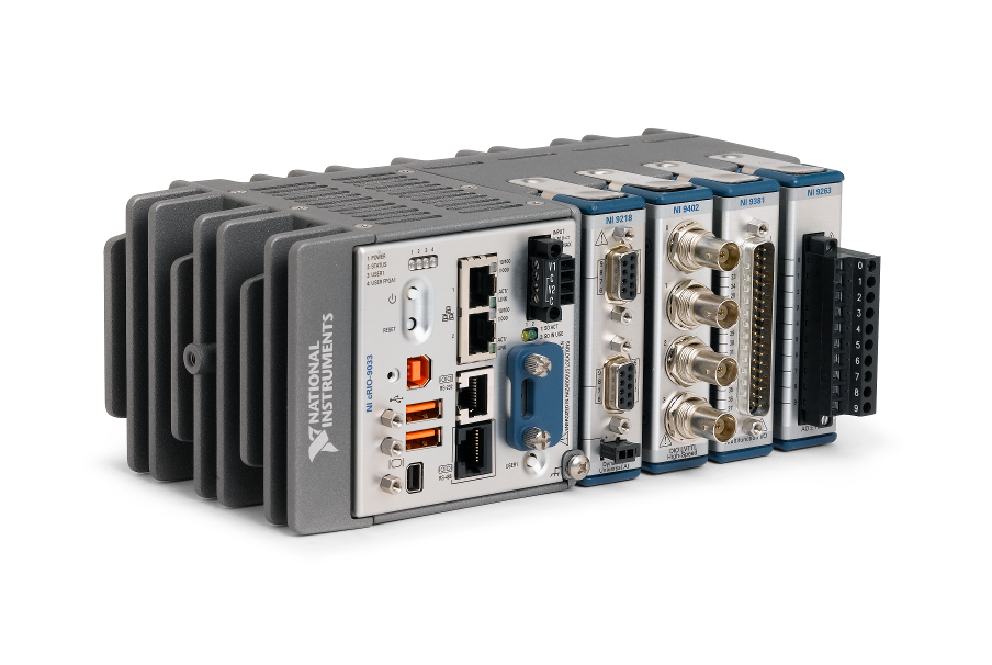
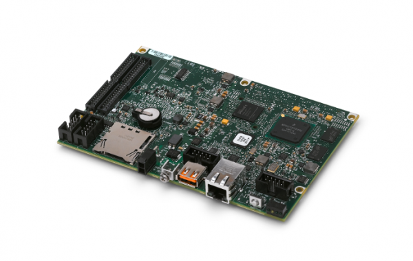
Embedded machine/equipment controller – both the NI cRIO & sbRIO have an FPGA and RT processor. For this use case, the embedded system is controlling some aspect of the industrial machine/equipment.
- It might control the tight tolerance timing of a particular manufacturing process,
- it might dynamically adapt production of the part to improve product quality,
- or it might control the operation of a piece of industrial equipment out in the field.
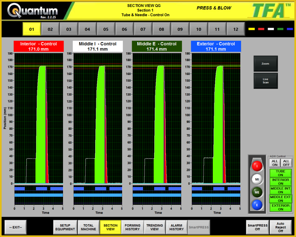
Some examples of machine control applications include:

Machine/equipment monitoring – this could include generalized monitoring of a machine or it could be more focused specifically on condition monitoring (see our guide Is condition monitoring right for you?) which generally has the objective of improving machine up-time/reliability and/or reducing maintenance costs and production loses. Some examples of machine/equipment monitoring applications include:

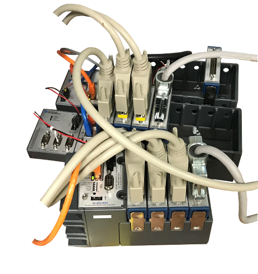
NI Hardware – we’re talking cRIO & sbRIO
If you’re interested in LabVIEW-based industrial automation, you’re likely going to need NI hardware in order to take advantage of tightly integrated I/O and deterministic processing. This will usually take the form of either a CompactRIO or a Single-Board RIO /SOM.
Why would you choose one over the other? Our recommendation would generally be to default to the cRIO unless a critical requirement drives you into the sbRIO. There’s more details than provided here (feel free to reach out here if you want to discuss those details), but the decision process will usually be based on three criteria:
- Size / envelope – if your application requires a small envelope, the cRIO form factor may just be too big and you’ll be forced to go the sbRIO route.
- Production volumes – at some quantity, it’ll likely make more sense from a financial standpoint to use the sbRIO.
- I/O availability – depending on how much of what you need from an I/O (including comm. interface) standpoint is available either as a module or part of the base unit, the custom board non-recurring engineering design costs may sway you one way or another.
We love the cRIO and use it a LOT.
LabVIEW Real-time & LabVIEW FPGA
Maybe you’re thinking you’ll be doing industrial automation with just a desktop PC-based LabVIEW application. If that’s the case, we’re coming from two very different places. The kind of automation we’re talking about here utilizes one or both of the RT & FPGA capabilities of LabVIEW.
LabVIEW RT & LabVIEW FPGA can perform similar sorts of tasks, with the main differentiator being time-criticality. This tends to show up in the following ways, and the fuzzy division of timing generally looks as follows:
| Aspect of Time | Generally suited to RT | Generally suited to FPGA |
|---|---|---|
| Loop rates | < 1 kHz | 10s to 100s of kHz |
| Response time / latency | 100s of us to ms | 10s of us to 100s of ns |
| Synchronization | 10s of ms | 10s of ns |
| Cycle-to-cycle determinism (or “jitter”) | 10s of us to ms | 10s of ns |
LabVIEW RT is more apt to help you with tasks such as:
- Supervisory state/mode sequencing
- System configuration
- Web server for thin client
- Slow control algorithms
- Fault condition handling
- Moderate synchronization of signal I/O without HW clocking
While LabVIEW FPGA can help you with:
- Fast control algorithms
- Low latency between input and output
- Tight synchronization of signal I/O with HW clocking
- Tight cycle-to-cycle determinism
- Operator safety and equipment protection from fault conditions (no operating system to get in the way)
- Multi-channel deterministic I/O (dozens of channels)
We’ve used LabVIEW RT for more than 1,000 solutions and LabVIEW FPGA for more than 700 solutions (including test & embedded applications). Sorry, reading this sounds arrogant, but it’s not intended that way, just a proof point that we do have at least a clue when it comes to RT & FPGA usage.
LabVIEW Industrial Automation Gotchas
A PLC as a companion
While some might argue with this in some cases, we believe that there’s still a good place for a PLC as a companion to LabVIEW-based industrial automation applications. Namely, handling the very low level safety or mission-critical aspects of operation. Anything with an ESTOP, or safety-critical out-of-limit condition. PLCs are so bullet proof. Safety & reliability is what they do best. Let them do their job.
A PLC as a Better Fit?
There are some situations where an inexpensive PLC could be used instead of a cRIO for dealing with logic signals or slow analog IO. Of course, you’ll no longer be using LabVIEW as the core of your automation. Make sure you have a driving reason to justify using a cRIO or sbRIO over a PLC.
User Interface – Don’t bite off more than you can chew
Everyone has experience with smartphone apps that have very intuitive UIs. Users tend to think of those experiences when trying to communicate how they want their LabVIEW UI to look. Some of the LabVIEW controls are either lacking in capability or ability to customize relative to other programming languages.
One example is a table that allows different data types for each cell (string, numeric, enum…). There are a couple solutions in LabVIEW for this but they don’t look as nice. Sometimes a fancy UI isn’t worth the cost.
Another example is the tab control. You can set the tab control resize with a pane but you can’t have its contents resize with it. You’re also not able to add new tab pages during run-time.
If you’re not careful, you can end up spending more of your time programming UI features than any other part of the software.
Be careful about the size FPGA you select
When you’re developing with an FPGA, you’re essentially enabling various digital logic gates on the chip. It’s hard to tell what size FPGA you will need until after you have a design that works. There is not a good way to estimate the size of the FPGA needed until after the code is written. Maybe sometimes it’s obvious that you can get away with a smaller less expensive FPGA, like when all you’re doing is passing values between the IO and host. Other times you may think what you need to do is simple enough but you wind up needing to do a lot of division or increased clock rates and run out of resources. After the code is written you can try to compile for the intended target and if even after trying to optimize it doesn’t fit you can try the next one up and keep going until it finally fits. You then know what size FPGA you need.
If multiple systems are expected, consider prototyping with a device with a larger FPGA than you think you need. After the prototype is proven you might be able to go with a cheaper cRIO for the deployed systems.
When it comes to drivers and libraries, don’t reinvent the wheel
Often drivers or libraries are written from scratch when there is something out there that already exists and will work. One example is Modbus drivers. There are a few implementations that have been created by NI and are available for free on their website. A little more time spent on research can save a lot of development and testing time. Be mindful of buggy or incomplete drivers.
Not making error/event logging a top priority
Logging needs to be a first class feature. With headless controllers running for months at a time, it is very hard to diagnose issues, so having a robust log of both errors and events can help you reconstruct issues to support bug fixes. Don’t expect normal debugging tools to be helpful or even work at all for solving some of these transient issues. Monitor key metrics (memory, CPU, disk space, etc.) to look for trends that could lead to crashes or undesirable controller states. Logging can play a key role here.
Not thinking through Deployment
Deploying one system can be pretty straightforward, but replicating that for many systems will get time consuming and tedious. You’ll want the ability to deploy/update/maintain many devices at once and monitor their status.
How to get Help
If you’re looking for help with using LabVIEW for your industrial automation application, there are two things you’ll need to do: (1) develop a good set of requirements and (2) find a vendor capable of helping you (you can reach out to us here if you’d like to chat).
Requirements – When it comes to requirements, this is one of the more challenging topics in the world of engineering. It causes frustration from all parties involved. Learning to write even decent requirements takes a fair amount of effort. Sometimes people assume that LabVIEW is a simple tool and it should just work, when in reality it’s a complex development environment with powerful coding capacity that should be treated just like any other development environment, so requirements are very important.
The key aspects for good requirements are that they are (1) testable and (2) succinct. We’ve considered creating an example set of requirements to serve as a starting point to work from (if you’d be interested in us creating an example set of requirements doc, let us know here), but for now, we’ve created a template for you to start from. Go here to get it.
Finding a capable vendor – check out this Outsourcing Industrial Embedded System Development Guide. It shares 10 considerations before you have an embedded design company develop your industrial embedded monitoring or control system for you, including considerations like: How will the EDC support me once units are fielded? And How do I get a warm fuzzy that the EDC can solve my specific problem?

Outsourcing Industrial Embedded System Development Guide
Outsourcing Industrial Embedded System Development Guide
10 Considerations before you have an embedded design company develop your industrial embedded monitoring or control system for you.
Consideration – How do I get a warm fuzzy that the EDC can solve my specific problem?
This is the most straightforward for you when the EDC has done your exact application in your industry. However, given that the EDC is in the world of custom development, generally your design will be at least somewhat unique (if it’s not, it’s worth thinking about how you’re addressing a problem differently than someone that’s already in the market).
Why you should care
To get that warm fuzzy feeling that you’re after with the belief that the EDC will not only perform as needed, but that they’ve got your back and will actually challenge you on some of your thoughts on how to proceed.
Recommendation
- Project stats – find out roughly how many industrial embedded projects they’ve done.
- Case studies – look for them. Think beyond your specific application or industry, and ask yourself what similarities you see from level of complexity, mission criticality, and monitoring & control functionality standpoint. For example, it’s a pretty different thing to locally control a single manufacturing machine at fast loop rates than it is to remotely monitor multiple deployments of some industrial equipment.
- Capabilities bullets – look for them. It’s a pretty different level of capability to design a digital level shifting interface circuit than it is to be able to design a low noise 24-bit A/D multi-channel analog input circuit.
- Ask them what aspects of the project they feel least comfortable with. This will give you a feel for what they’re most concerned about, even if they feel comfortable with your project overall. This gives you thoughts on areas that you should pay close attention to during project execution.
Consideration – What language(s) will the EDC be coding in?
There are dozens of languages out there to write software applications. Many of them are not appropriate for embedded systems. Several are. Some of the more popular languages will include C/C++ for sequential processors and VHDL/Verilog for FPGAs.
Why you should care
Supportability – If you need to be able to make tweaks on your own post-delivery then you’ll need the IDE software to do so.
Portability – If you need to switch EDCs or switch tool chains you’ll need to find an EDC that supports the selected language(s).
Recommendation
- Do a sanity check search on the web to get a feel for how common the languages are that your EDC is proposing. Don’t be afraid to ask the EDC why they prefer the language that they do. This can give you some good insight.
- Make sure you understand what files will be provided to you, and set them as deliverables. At a minimum, you’ll want to request all software/firmware source code files (e.g., .c, .vhd, etc.). It can also be helpful to understand what versions of which IDEs are being used.
Consideration – What circuit board design files will you be provided by the EDC?
Chances are you won’t be able to modify the hardware design yourself, and it’s unlikely that you’ll convince a new EDC to take the design files, import them, and modify that design (there are just too many variables (e.g. libraries) in the setup of the design to trust that everything will just work). However, it’s very helpful to have the schematic, layout, and BOM (Bill Of Materials) files to serve as breadcrumbs in reverse engineering much of the design intent in order to create a new version of that design. Chances are that, even with the right files, they won’t be able to import the design and start from there. They’ll have to start the schematic/artwork from scratch.
Why you should care
Supportability – if you need to create a new version of the design and you want to use a different EDC, having the right files will provide some breadcrumbs for them to assist in understanding design intent.
Recommendation
Make sure you understand what files will be provided to you, and set them as deliverables. You’ll want to ask for:
- Schematic capture files
- Artwork files
- Fabrication & assembly files (Gerbers)
- BOM (Bill Of Materials)
Consideration – What hardware platform does the EDC use as their core building block?
There are lots of options out there for hardware platforms. Depending on your application, you may be considering the likes of PC-104 stacks or similar, RasPi, Arduino, NI RIO, Avnet PicoZed, a fully custom board, or maybe even a PLC. Be careful here, performance, ruggedness and reliability will vary greatly. Choose cautiously.
Why you should care
You’re naturally going to care about the performance and environmental specifications of the hardware, so we won’t even get into that.
Lifecycle maintenance & obsolescence – while not the most fun aspect of the design cycle to deal with, this is an inevitable part. The last thing you want is to be in a successful mature production phase only to find out that critical components are going obsolete and you have no path forward.
Future upgrades – if you’ll need to upgrade your design in the future, maybe with an expanded, limited, or just different, feature set.
Recommendation
- Find out why the EDC thinks the selected hardware stack is a good choice for your scenario.
- For lifecycle maintenance, find out about the manufacturers product lifecycle plans. Ask the EDC about how they handle and support life cycle management. In other words, who watches out for parts going obsolete? Who recommends last time buys?
- If you care about future expansion possibilities, ask about: Processor headroom, Spare I/O, Controller variants.
- Check out this white paper for details on finding a good spot for you on the COTS-custom spectrum. There are off-the-shelf options out there. You generally only want to do as much custom design as needed, given your performance requirements, projected volumes, and time-to-market constraints.
Consideration – What IP is the EDC bringing to the table?
Since you’re developing a custom system, there will likely be many custom aspects to the controller that need to be developed from scratch. However, often times, companies develop their own IP (both hardware and software) for use across multiple projects as building blocks.
Why you should care
There may be limitations associated with the utilization of the EDC’s IP. Maybe you pay royalties on units sold. Maybe you retain rights to use the code as-is, but not to modify.
Generally speaking, the more IP the EDC has, the less NRE you’ll spend. Granted, the EDC is going to want to recoup some of their development costs, but chances are, pre-developed IP will save you in development costs.
Recommendation
Ask for the EDCs IP licensing agreement and learn what the terms are.
Consideration – What IP will be developed as part of this project?
How much do you care about protecting your IP? Maybe you’ve developed a pretty cool algorithm that you’d like to retain ownership of. Maybe you’re not doing anything horribly unique at the controller level, and maybe the EDC would like ownership of that IP for other future projects.
Why you should care
This can limit your use, or use by the EDC.
It also can affect pricing for the project and subsequent sales. If the EDC finds the IP valuable for them, they may be willing to drop the price on the development work.
Recommendation
- Articulate IP rights and ownership as part of the contract.
- Consider a patent for a truly novel idea.
Consideration – How deep is the EDC’s bench?
You’re buying a capability. The end product doesn’t exist yet. Your needs relating to flexibility, responsiveness, risk reduction, and price sensitivity will drive what you care about here.
Why you should care
You want your project to be completed, and you want support when you have questions.
Recommendation
You generally are going to trade risk for price here. You have to decide what balance you’re comfortable with.
Consideration – How will the EDC support me once units are fielded?
Depending on our scenario this could mean different things:
- Like it or not, you’re likely going to be dealing with bugs and/or warranty returns in the field at some point.
- You may have situations where different customers want different features.
Why you should care
When you’ve got fielded units, you don’t want to end up stranded, because you’ll end up with unhappy customers quickly.
Recommendation
- Define the level of support desired up front before development begins. Do you want a certain level of support at a fixed price? Are you happy with T&M support on an as-needed basis?
- If different features are likely desired by different customers, and those features are understood ahead of time, the embedded controller can be architected differently, so have this discussion before development begins.
Consideration – How important does my project seem to the EDC during the sales process?
Do you feel the love, or are you feeling more like a bother? If you’re feeling like you’re bothering the EDC before they win your business, how do you think things are going to go after they get your business? Of course, not everyone can be top priority, otherwise there would be no top priority, but you don’t want to be at the bottom of the barrel either. Somewhere in the middle may be just fine depending on your scenario.
Why you should care
This can be a good indicator of how they will treat you during project execution.
Recommendation
Sniff out where you fit in the priority of all their other projects. Unfortunately, there’s no easy mechanism here. You can ask them, but you may not get the most honest answer. Some subtle indicators to look for to help see where you fit:
- Tone of voice during conversations.
- How often are you being asked to re-schedule because something else came up after you locked in a meeting time? This can happen unavoidably, but generally shouldn’t happen more than once during the sales phase of the project.
- How long does it take for them to respond to your emails? Generally, initial emails should be answered within ~24 hours. Further down, when the depth of technical detail is significant, it may require a handful of days for a detailed response.
- Try to get references from prior clients, just be aware that the EDC might not be able to give them due to NDAs.
Consideration – Am I willing to invest time and energy into requirements development?
Requirements are the mechanism for communicating what the embedded controller needs to do. This step is often seen as not being value add, because you already know what you need (at least at a high level) in your head. You’ll want to use the requirements to create an acceptance test plan.
Why you should care
At the end of the day, you want your controller to work in a particular way. The way to validate and verify it is by testing it. In order to test, you need testable requirements.
Recommendation
Check out this industrial embedded requirements and spec template. You don’t need to necessarily capture everything on the first iteration. Take two hours to capture what you know as well as TBDs, then engage the embedded design house in a conversation and iterate from there.
As companies hone in on the core value they bring to the market, outsourcing various components and subsystems becomes a popular option. If you’re considering outsourcing the development of your industrial embedded monitoring or control system, it’s likely that either your internal resources are overloaded or perhaps your company doesn’t have the capability in-house.
If you’re considering us, you can learn some of the basics about us here. If you’d like to see what we’d propose to solve your industrial embedded problem, reach out here to chat:
Webcast – Bring I/O Into and Out of Your Measurement & Control System
Webcast – Bring I/O Into and Out of Your Measurement & Control System
People often think about the core components of a control system: the control algorithm, the sensors, and the actuators.
There is a lot to consider in between. In this webcast we’ll talk about the realities associated with bringing signals into, and providing outputs from, your measurement and control system. At a high level, we’ll learn abou the importance of interfaces, obviously from a technical perspective, but also from a business perspective.
| Key topics discussed: |
|---|
| Signal Conditioning do’s and don’ts |
| Sampling considerations |
| Pre-processing tips |
| We’ll answer questions like: |
|---|
| What are typical considerations when selecting a sensor? |
| What are the main stages for interfacing to a control algorithm? |
| What are the most important aspects of preserving an analog signal? |
| What are some basic signal sampling considerations to keep in mind? |

Top 5 Embedded System Design Fails
Top 5 Embedded System Design Fails
Common Pitfalls and How To Avoid Them
Are your embedded design projects hitting roadblocks? Make sure you’re not making these common mistakes.
Introduction
In the embedded system world, beginning a new design project can be exciting. It’s easy to get swept away with the possibility of creating an innovative product that the market has not seen before, and that will exceed the customer’s expectations.
But prior to starting work, it’s essential for project leaders to consider all available skill sets within the design team. It’s equally important to have a clear understanding of what specific vendors can offer, in terms of the tools the vendor will be using, and the level of service they can be expected to deliver.
Additionally, project leaders need to consider—of course—the customer’s requirements around product specifications and the project deadline. For this reason, it’s essential to capture customer requirements in their entirety prior to starting the project, and to be sure the entire design engineering team is aware of those requirements. Lastly, solid and open inter-team communications, and the ability to coordinate widely varying personalities on the project, are also critical.
Simply put, ensuring a design project’s ultimate success requires an understanding of how to bring all of these things together.
Overlooking the intersection of all of these elements leads to errors, cost overruns, missed deadlines and a poorly designed product. A delivered product does not equal a successful product. And a completed project is not successful if your team was rushed, stressed and frustrated.
This white paper discusses the top five embedded system design fails and how you can avoid them.
Fail #1: choosing the wrong tools
It’s not unusual for some team members to have stronger skill sets in some areas than in others. After all, different embedded systems require that your team employ different skills, based on whether the project calls for CAD or FPGA design software, for example, or whether the software language environment will be Microsoft (.Net), Oracle (Java), National Instruments (LabVIEW), or free and open source (Python, Ruby, GCC, etc.).
A common design fail is to choose one set of tools over another without considering what is both best for the success of the project and how many of your design engineers are knowledgeable about that particular tool. You should not choose tools based on who speaks first or most loudly in a project meeting, but it’s not unusual for tools to be chosen this way.
Do not fall into the temptation of a vendor’s persuasive sales pitch. Many will claim that they are faster, offer the best pricing, etc. If your team is inexperienced in using that vendor’s tools, the project timeline and budget can grow exponentially. On-the-job training can be costly and time-consuming, since your team members may spend more time learning new software or language than they do actually working on the design itself.
Conversely, sometimes it does make sense to train team members on a particular tool, as they can use this new knowledge in other projects. Most engineers like to learn new skills—and should. If training is a value-add for the team, plan to budget that as a separate line item, and on a separate schedule, from the project itself.
The best approach is to consider all readily available skill sets and tools, and to make decisions based on what will most efficiently and cost-effectively contribute to the project’s success.
Fail #2: choosing the wrong vendor
No two vendors are alike, but another common design fail is choosing one before considering the software they will be using, the inevitable bugs that software will introduce, and how capable your team is of fixing those bugs. Again, will the required fixes add time to the project that the schedule does not allow?
Another key vendor consideration is the service experience. Will the vendor be likely to work well with your team, be responsive and meet all necessary milestones? Will the work quality meet the required standards? If you have a smaller company, will the vendor be sympathetic to the limitations of your team’s size, skills and time constraints?
To avoid overlooking these key considerations, it’s best to understand the specifics of what the vendor is providing, the pain points or idiosyncrasies of that vendor (because there are always some to overcome), and to choose the vendor that best meets your requirements for both the product and the service experience.
Fail #3: incorrect resource allocation
Another design fail is overlooking the ability to outsource all or part of a project. Many organizations take the approach of always keeping all projects in-house. The goal, of course, is to maximize profit by controlling overhead costs. But forcing a small, already overworked design team to take on another large project will overburden resources. This not only leads to burnout within your team, it often sacrifices product quality due to unavoidable mistakes.
Conversely, in larger organizations, where design engineering costs can run into $100’s per hour, outsourcing all or part of a project can help alleviate budget overruns. For example, as mentioned previously, will the new project require additional training? It can make more sense to enlist a ready expert to take the helm.
The most strategic approach is to establish processes for considering available time and skill sets, and to assign projects in-house accordingly, or outsource when your resources or budget require it.
Fail #4: misunderstanding project requirements
Failing to conduct thorough customer interviews at the requirements-gathering phase is another common mistake. For example, it’s not only important to understand requirements around product color or weight, but also to understand specifics and reasons behind those requirements. “The communications bus shall be MIL-STD-1553” is an example of a good requirement.
On the other hand, sometimes the requirements are much less clear. “The embedded system will have high up-time.” How high? “The system will not weigh too much.” How much is too much? Is there wiggle room in either requirement? Understanding the reasons behind the product specifications can help avoid disastrous outcomes.
The smart approach to requirements-gathering is to involve all team members at the outset of your requirements-gathering phase. This should include the design engineering team, the management team, and the customer. First-hand knowledge is crucial, because vagary in the requirements-gathering phase leads to errors.
Fail #5: lack of communication
This is perhaps the most common design fail and the most difficult to avoid. It’s a universal truth that a talent for design does not equal good communication skills. Engineers of every type—including design engineers—are not immune to challenges around communication. But a lack of communication in a project can lead to a design failure in the end product. Overcoming this challenge requires a three-pronged approach.
- First, it’s critical to make sure that for each project there is a strong manager or project lead in place to assist where needed. This person should be adept at proactively facilitating communication and working with individual team members to improve on areas of weakness. Is a team member unable to communicate effectively via email? Is another team member particularly reserved in a public forum, and unable to speak effectively (or at all) in meetings? Coaching can help. Of course, this always requires a willingness from the team member to hone those communications skills. It can’t be overemphasized that individual team members must take responsibility for communicating effectively as well.
- The second essential is to have the manager or project lead assist in choosing the right communication format for each person on the project, whether that’s email, in-person meetings, conference calls, etc. (Just because someone is being coached doesn’t mean he or she will ever really excel in all communication areas).
- Lastly, the importance of open and honest communications between management and engineering resources cannot be understated. This necessitates management’s willingness to consider whether the team is prepared to meet all the customer’s requirements for both specifications and timelines. The engineering team must feel comfortable providing feedback on what they think they can and cannot do within the specified time period—and to suggest outsourcing when necessary—without fear of losing their job.
Choose your failures carefully
Not all design fails spell disaster for a project. After all, some mistakes are necessary to gain knowledge for future projects. Yet other fails, like those mentioned above, lead to mistakes, cost overruns, damaged morale, unnecessary re-work and a dissatisfied customer. To ensure a project’s success, it’s critical to know the difference between the former and the latter.
Next Steps
If you’d like someone to take the industrial embedded development off your plate, you can learn more about how we can help or reach out to start a conversation.
If you’re deep into learning mode, check out these resources:

FPGA Gotchas – The Top 11 Gotchas when developing with an FPGA

FPGA GOTCHAS -The Top 11 Gotchas when developing with an FPGA
Some of the topics we’ll cover:
- How to put yourself in the right mindset as a developer
- Why the bulk of your algorithm will generally NOT be the bulk of your development time
- Why it’s important to not make fun of the software guy
So you’re considering an FPGA for your next project… Excellent. The technology is pretty cool. However, before you take the plunge, you’ll want to consider these realities.
It’s worth noting that this is a complex topic, and as such, some topics are not covered, some are just introductory, and others will evolve over time. This paper should still give you a lot of helpful information if you’re new to the world of FPGAs.
If you feel uncomfortable about what’s under the hood of an FPGA, check out our FPGA Basics – A Look Under the Hood white paper.
Gotcha #1: Thinking that you’re writing software

Get out of the software mindset – You’re not writing software. Let me say that again because this is the single most important point if you’re working with FPGAs. You-are-NOT-writing-software. You’re designing a digital circuit. You’re using code to tell the chip how to configure itself. Now, before someone says it, yes, when you’re coding up one of the microprocessor cores within the FPGA, then of course you’re writing software, but that’s not what we’re talking about here. We’re talking about when you’re coding the digital logic.
Gotcha #2: Assuming the bulk of your algorithm is the bulk of development time

When developing with an FPGA, the core processing functions (e.g. an FFT) actually only occupy a small fraction of the overall workload. It’s generally all the other non-core elements that end up chewing up a large fraction of your development time.
Some example functional blocks that will take large chunks of your overall effort:
- Interfacing to various external memory chips
- Creating a communications bus
- Error checking
- Developing a configuration architecture.
Gotcha #3: Not paying enough attention to timing stability
 This is a critical aspect of developing with FPGAs. Instability can cause the FPGA to basically lose its mind, rendering outputs in unknown states either as a glitch or permanently (until reset or reload). Good coding practices and knowing the limits from a clock frequency and part fullness standpoint will go a long way toward reducing your risk.
Gotcha #4: Not worrying about cyber security
 A lot of FPGAs embed Ethernet cores, common processor cores, and some are even running an OS, making it so FPGA-based (sometimes referred to as SoC (system on a chip)) solutions look like another computer on the network. This increases their vulnerability to more traditional attack methods. Take the time to understand your risks and mitigate them. Obscurity is generally NOT a solid security approach (check out The Great Debate: Security by Obscurity). Here are two articles to get you thinking:
- How to build an FPGA-based I&C
- Microsemi Steps Up Its Cyber Security Leadership in FPGAs: SmartFusion2 SoC FPGAs and IGLOO2 FPGAs Enhanced with Physically Unclonable Function Technology
Gotcha #5: Not understanding the risks for safety-related applications
 If you’re considering an FPGA within a safety-related application, you need to understand the risks that you’re incurring.
Here are a few articles to get you thinking:
- Safe FPGA Design Practices for Instrumentation and Control in Nuclear Plants
- SRAM-Based FPGA Systems for Safety-Critical Applications: A Survey on Design Standards and Proposed Methodologies
- Xilinx Reduces Risk and Increases Efficiency for IEC61508 and ISO26262 Certified Safety Applications
Gotcha #6: Not having at least one driving Algorithmic reason to use an FPGA

Seems obvious, but don’t just get sucked in by the cool factor of what an FPGA can do. Much of what will make it worthwhile to utilize an FPGA comes down to the low-level functions being performed within the device. There are roughly four processing/algorithm attributes that FPGAs are generally well-suited for, and there are another handful of algorithmic and non-algorithmic attributes that make an FPGA less desirable. These are covered in our FPGA Basics – A Look Under the Hood white paper.
Gotcha #7: Not doing design reviews:
Seriously. Design reviews are an important part of this process, and are not just for newbies. The number, depth, and focus of design reviews can vary depending on the:
- Complexity of the design
- Criticality of the function or system
- Experience of the designer.
Reviews to consider include:
- Functional overview
- Detailed design
- Code
- Simulation
- Unit test.
Gotcha #8: Jumping right into coding
 Since you’re essentially designing a digital circuit, as a beginner, you should not begin coding in any language until you’ve created a block diagram for your design. The level of detail that you should show varies based on the complexity of the design, but consider creating detailed design block diagrams at the gate/FF level for at least the first 20 or so designs that you create. After that, you may evolve to sketching out your design at a higher level, but it’s great practice to get used to seeing your designs closer to what they actually are, digital circuits.
Also consider creating timing diagrams where appropriate. These are especially useful in designs where one output needs to be asserted relative to another output, or when feedback or handshaking is involved.
Another useful way to view some elements of your design is by creating state machines and flow diagrams.
Gotcha #9: Trying to use all of the FPGA!
In general, you want to use less than 100% of the part. The amount that you’ll want to keep in reserve depends on several factors, with significant factors including:
- The generation/architecture of FPGA being utilized
- Your code quality
- The FPGA clock rate
The fuller your part is, the longer the build process (compile, synthesis, place, route, etc.) will take. The reason this is a useful note, is that build times don’t take seconds. Depending on many factors, they can take 20 minutes, or four hours. In some cases it may fail to build at all, or worse yet, build, but be unstable, wasting countless hours in the lab.
Gotcha #10: Not planning for Enough Bugs

Something about that feels wrong on first read, because who actually plans for bugs? You should. If you do it will be one of the most stress-relieving things you do, and you’ll thank me later. You’ll get many of the most basic level 1 bugs out during simulation, but at some point there will be a driving reason where you’ll have to move out to the lab and integrate your part of the world with the rest of the system being developed. This is where those famous words “But it worked fine in simulation…” come into play.
The disadvantage of a run-of-the-mill basic sequential processor is that only one operation is executing at any point in time. The advantage of a sequential processor is that only one operation is executing at any point in time. When it comes to debugging, the sequential nature of the basic processor makes life easier than debugging the parallel nature of the FPGA. While the simulation environment offered impressive visibility, now that you’re moving into hardware, your visibility into what’s going on decreases significantly.
Plan for a lot of bugs. Take a couple hours and think through other bugs you’ve dealt with as an engineer. Now triple that number (I’m making this multiplier up of course). If you’re a newbie developer, you need to pull in someone that has experience with FPGA development to help with this estimate. You’ll be wrong, but you’ll be better off than if you hadn’t thought this through. Here are a few tips on debugging to help you along the way: Six debugging techniques for embedded system development.
Intermittent bugs are common within FPGAs. They can be affected by temperature, humidity, the phase of the moon (I may be exaggerating a bit there, but sometimes I wonder).

The logic analyzer is your eyes into the inner workings of the FPGA. You can view outputs of course, and you can create test points to go to a testpoint header, but you have to be able to probe all of those points, so you’ll probably need a logic analyzer, which can get very pricey (if you’re looking for an inexpensive logic analyzer, check this out: https://www.saleae.com/ , and similar). A logic analyzer is a very important tool for FPGA-based development.
An internal logic analyzer can be helpful as well, at least in some scenarios. You may be able to get away with embedding test resources into your device (e.g. Xilinx has the Integrated Logic Analyzer), but this will utilize FPGA logic and memory resources, and is often challenging to see enough breadth or depth about what’s going on inside your FPGA. However, generally these tools are better for augmenting a true logic analyzer, as opposed to replacing them outright.
Gotcha #11: Making fun of the software guy!
The software guy (or girl of course; the term “guy” is used here androgynously) is your best friend – If your FPGA interfaces to a higher level supervisory sort of processor and/or it provides the UI, the software guy can do things to help make your life a lot easier. A couple of the more major categories include:
- Engineering debug panels – chances are the information you need to view is not the same as what the end-user needs to view. Having a debug panel can save you significant time, effort, and frustration.
- Special debug functions and modes – maybe there is some routine that software normally runs through with steps 1-12, but maybe you want to be able to run just step 3 and 4 repeatedly, or maybe just step 7 once. Or perhaps software can add a special function to keep track of the content or frequency of messages that you’re sending to it and set a trigger when something unexpected happens.
Work with the software developer early on to see how you can work together to facilitate the integration and debug process, and remember that it goes both ways. Chances are there is additional functionality that you could add to aid in their debug process as well.
Next Steps:
If you’ve made it to this point in the paper, maybe you’re thinking that an FPGA may be a good fit for your upcoming application. Reach out to us here if you want to chat about your specific needs. If you’d like more useful info on industrial embedded, check out our resources page. If you’re looking for useful info on test systems, go here.
Deep into learning mode? Check out these resources:
- When is an FPGA Worth it and When is it NOT – when developing an Industrial Embedded System
- Using an NI CompactRIO for Industrial Embedded Monitoring & Control applications
- Outsourcing Industrial Embedded System Development Guide
- LabVIEW Industrial Automation Guide
- Online Monitoring of Industrial Equipment / Machines / Systems
- FPGA Basics for Industrial Applications

FPGA Basics – A Look Under the Hood

FPGA Basics – A Look Under the Hood
An introductory look inside Field Programmable Gate Arrays. We’ll go over:
- Strengths & Weaknesses of FPGAs
- How FPGAs work
- What’s inside an FPGA
So you keep hearing about FPGAs being utilized in more and more applications, but aren’t sure whether it makes sense to switch to a new technology. Or maybe you’re just getting into the embedded world and want to figure out if an FPGA-based system makes sense for you or not.
This paper provides an overview of some of the key elements of FPGAs for engineers interested in utilizing FPGA-based technologies. It’s worth noting that this is a complex topic, and as such, some topics are not covered, some are just introductory, and others will evolve over time. This paper should still give you a lot of helpful information if you’re new to the world of FPGAs.
What are the most important things you should know right away?
- Get out of the software mindset – You’re not writing software. Let me say that again because this is the single most important point if you’re thinking about working with FPGAs.
You-are-NOT-writing-software.

You’re designing a digital circuit. You’re using code to tell the chip how to configure itself.
- Plan for lots of bugs – yes, plan for them. They are going to happen. Way more than you expected. If you’re a newbie developer, you need to pull in someone that has experience with FPGA development to help with this estimate.
- Application-specific realities – you ought to concern yourself with realities revolving around cyber security and safety, as FPGAs are a different animal than what you’re likely used to.
What is an FPGA?
An FPGA is a (mostly) digital, (re-)configurable ASIC. I say mostly because there are analog and mixed-signal aspects to modern FPGAs. For example, some have A/D converters and PLLs. I put re- in parenthesis because there are actually one-time-programmable FPGAs, where once you configure them, that’s it, never again. However, most FPGAs you’ll come across are going to be re-configurable. So what do I mean by digitally configurable ASIC?
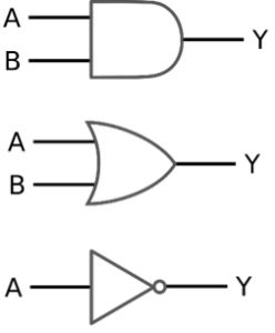
I mean that at the core of it, you’re designing a digital logic circuit, as in AND, OR, NOT, flip-flops, etc. Of course that’s not entirely accurate and there’s much more to it than that, but that is the gist at its core.
The players –
There are currently two big boys: Altera (part of Intel) and Xilinx, and some supporting players (e.g. Actel (owned by Microsemi)).
The main underlying technology options are SRAM-based (this is the most common technology), flash, and anti-fuse. As you might imagine, each option has its own pros and cons.
Strengths / best suited for:
Much of what will make it worthwhile to utilize an FPGA comes down to the low-level functions being performed within the device. There are four processing/algorithm attributes defined below that FPGAs are generally well-suited for. While just one of these needs may drive you toward an FPGA, the more of these your application has, the more an FPGA-based solution will appeal.
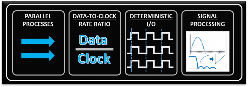
- Parallel processes – if you need to process several input channels of information (e.g. many simultaneous A/D channels) or control several channels at once (e.g. several PID loops).
- High data-to-clock-rate-ratio – if you’ve got lots of calculations that need to be executed over and over and over again, essentially continuously. The advantage is that you’re not tying up a centralized processor. Each function can operate on its own.
- Large quantities of deterministic I/O – the amount of determinism that you can achieve with an FPGA will usually far surpass that of a typical sequential processor. If there are too many operations within your required loop rate on a sequential processor, you may not even have enough time to close the loop to update all of the I/O within the allotted time.
- Signal processing – includes algorithms such as digital filtering, demodulation, detection algorithms, frequency domain processing, image processing, or control algorithms.
Weaknesses / not optimal for:
With any significant benefit, there’s often times a corresponding cost. In the case of FPGAs, the following are generally the main disadvantages of FPGA-based solutions.
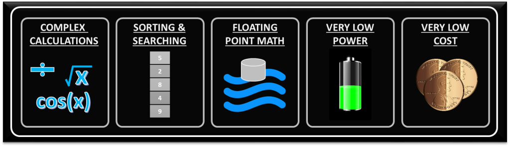
- Complex calculations infrequently – If the majority of your algorithms only need to make a computation less than 1% of the time, you’ve generally still allocated those logic resources for a particular function (there are exceptions to this), so they’re still sitting there on your FPGA, not doing anything useful for a significant amount of time.
- Sorting/searching – this really falls into the category of a sequential process. There are algorithms that attempt to reduce the number of computations involved, but in general, this is a sequential process that doesn’t easily lend itself to efficient use of parallel logical resources. Check out the sorting section here and check out this article here for some more info.
- Floating point arithmetic – historically, the basic arithmetic elements within an FPGA have been fixed-point binary elements at their core. In some cases, floating point math can be achieved (see Xilinx FP Operator and Altera FP White Paper ), but it will chew up a lot of logical resources. Be mindful of single-precision vs double-precision, as well as deviations from standards. However, this FPGA weakness appears to be starting to fade, as hardened floating-point DSP blocks are starting to be embedded within some FPGAs (see Altera Arria 10 Hard Floating Point DSP Block).
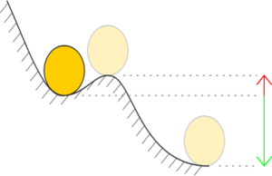
- Very low power – Some FPGAs have low power modes (hibernate and/or suspend) to help reduce current consumption, and some may require external mode control ICs to get the most out of this. Check out an example low power mode FPGA here. There are both static and dynamic aspects to power consumption. Check out these power estimation spreadsheets to start to get a sense of power utilization under various conditions. However, if low power is critical, you can generally do better power-wise with low-power architected microprocessors or microcontrollers.
- Very low cost – while FPGA costs have come down drastically over the last decade or so, they are still generally more expensive than sequential processors.
How Does an FPGA work?
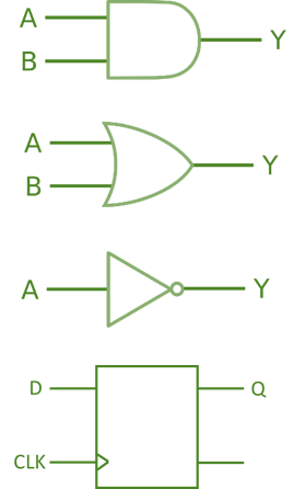
You’re designing a digital circuit more than anything else, basically at one layer of abstraction above the logic gate (AND, OR, NOT) level. At the most basic level, you need to think about how you’re specifying the layout and equations at the level of LUTs (Look-Up Tables) and FFs (Flip-Flops).
Otherwise you’re circuit can get very large and slow very quickly. You’ve got a very detailed level of control at your fingertips, which is very powerful, but can be overwhelming, so start slow. You’ll be determining the # of bits, and exact math / structure of each function.
An FPGA is a synchronous device, meaning that logical operations are performed on a clock cycle-by-cycle basis. Flip-flops are the core element to enabling this structure.
In general, you’re going to put digital data into an FPGA and get digital data out of it through various low-voltage digital I/O lines, sometimes many bits in parallel (maybe through one or more A/D converter outputs or an external DRAM chip), sometimes through high-speed serial I/O (maybe connecting to an Ethernet PHY or USB chip).
What’s inside – Core components (or at least what everyone likes to think about):
LUT (Look-Up Table) –
The name LUT in the context of FPGAs is actually misleading, as it doesn’t convey the full power of this logical resource. The obvious use of a LUT is as a logic lookup table (see examples here and here), generally with 4 to 6 inputs and 1 to 2 outputs to specify any logical operation that fits within those bounds. There are however two other common uses for a LUT:
- LUT as a shift register – shift registers are very useful for things like delaying the timing of an operation to align the outputs of one algorithm with another. Size varies based on FPGA.
- LUT as a small memory – you can configure the LUT logic as a VERY small volatile random-access memory block. Size varies based on FPGA
FF (Flip-flop) –
Flip-flops store the output of a combinational logic calculation. This is a critical element in FPGA design because you can only allow so much asynchronous logic and routing to occur before it is registered by a synchronous resource (the flip-flop), otherwise the FPGA won’t make timing. It’s the core of how an FPGA works.
Flip-flops can be used to register data every clock cycle, latch data, gate off data, or enable signals.
Block Memory –
It’s important to note that there are generally several types of memory in an FPGA. We mentioned the configuration of a LUT resource. Another is essentially program memory, which is intended to store the compiled version of the FPGA program itself (this may be part of the FPGA chip or as a separate non-volatile memory chip). What we’re referring to here though, is neither of those types of memory. Here we’re referring to dedicated blocks of volatile user memory within the FPGA. This memory block is generally on the order of thousands of bits of memory, is configurable in width and depth, and multiple blocks of memory can be chained together to create larger memory elements. They can generally be configured as either single-port or dual-port random access, or as a FIFO. There will generally be many block memory elements within an FPGA.
Multipliers or DSP blocks –
Have you ever seen the number of digital logic resources that it takes to create a 16-bit by 16-bit multiplier? It’s pretty crazy, and would chew through your logical and routing resources pretty quickly. Check out the 2-bit by 2-bit example here: https://en.wikipedia.org/wiki/Binary_multiplier. FPGA vendors solve this problem with dedicated silicon to lay down something on the order of 18-bit multiplier blocks. Some architectures have recognized the utility of digital signal processing taking place, and have taken it a step further with dedicated DSP (Digital Signal Processing) blocks, which can not only multiply, but add and accumulate as well.
I/O (Input/Output) –
If you’re going to do something useful with an FPGA, you generally have to get data from and/or provide data outside the FPGA. To facilitate this, FPGAs will include I/O blocks that allow for various voltage standards (e.g. LVCMOS, LVDS) as well as timing delay elements to help align multiple signals with one another (e.g. for a parallel bus to an external RAM chip).
Clocking and routing –
This is really a more advanced topic, but critical enough to at least introduce. You’ll likely use an external oscillator and feed it into clocking resources that can multiply, divide, and provide phase-shifted versions of your clock to various parts of the FPGA.
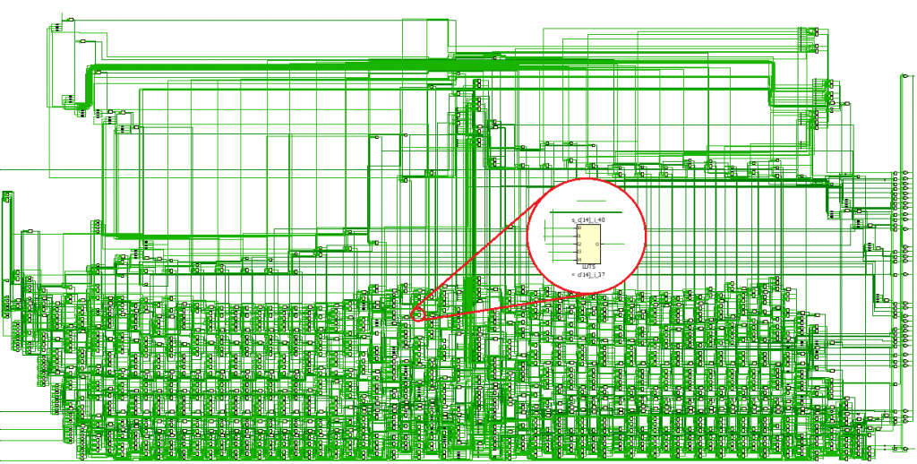
Routing resources not only route your clock to various parts of the FPGA, but also your data. Routing resources within an FPGA are one of the most underappreciated elements, but so critical. Check out this sea of madness:
What’s Inside – Advanced components
Hard cores – These are functional blocks that (at least for the most part) have their own dedicated logical resources. In other words, they are already embedded into your FPGA silicon. You configure them with various parameters and tell the tools to enable them for you. This could include functions such as high-speed communications (e.g. high-speed serial, Ethernet), low-speed A/D converters for things like measuring slowly varying voltages, and microprocessor cores to handle some of the functions that FPGA logic is not as well suited for.
Soft cores – These are functional blocks that don’t have their own dedicated logical resources. In other words, they are laid out with your core logic resources. You configure them with various parameters and tell the tools to build them for you. This could include everything from DDR memory interfaces to FFT cores to FIR filters to microprocessors to CORDICs. The library of available soft cores can be impressive. On the plus side, you don’t have to take as much time to develop these cores. On the negative side, since you won’t know the intricacies of the design, when you plop it down and it doesn’t work, it will generally take you longer to figure out why.
Next Steps
Thinking that an FPGA is a good fit for your application? Curious what we would do? If you work for a US-based manufacturer, reach out if you want to discuss.
A few other resources you might be interested in:
- Want to see what you can do with LabVIEW FPGA?
- LabVIEW FPGA– The Good, the Bad, and the Ugly
- FPGA Gotchas -The Top 11 Gotchas when developing with an FPGA
- HDL FPGA Development – The Good, the Bad, and the Ugly
Getting Started with Online Condition Monitoring

Online Condition Monitoring – How to Get Started – A Practical Guide for OEMs
Do you have a pretty good sense that Online Condition Monitoring can help you out, but aren’t sure where to begin or what pitfalls you might come across?
This guide will offer up steps you can take to start moving forward. We’ll provide info on:
- How to go about building a business case for OCM
- Deciding what to monitor with your OCM sub-system
- How to develop a Pilot program for OCM
INTRODUCTION
Let’s start by defining online condition monitoring. In this context, online condition monitoring (OCM) is defined as the utilization of measurement hardware and software to continuously check the state of a system, a machine, or a process, generally with the end goal of reducing downtime, increasing efficiency, or reducing waste. These goals are accomplished by producing a set of indicators (events, faults, and alarms) that suggest an action, such as look further into a potential problem, shut down a piece of equipment, perform maintenance, or collect additional data.
It’s also important to define and differentiate an OEM (Original Equipment Manufacturer) versus an end-user of CM (Condition Monitoring). If you manufacture industrial equipment, machines, or infrastructure and have interest in putting condition monitoring into systems that you sell, you’re considered an OEM. If on the other hand, you work at a manufacturing / generation / distribution / processing plant and have interest in putting condition monitoring into systems you operate internally, you’re an end-user. This guide is focused on the OEM scenario.
BUILDING THE BUSINESS CASE
 If you have already been given the go-ahead to implement OCM, or if you already know how to justify OCM, then you can skip this section. For those of you that are not sure how to go about justifying OCM, my suggestion is this: utilize the minimum amount of effort necessary. If it makes sense to spend weeks crunching numbers, then so be it, but if it makes sense to tie OCM into a corporate-level initiative (e.g. around efficiency or quality), then go that route.
The level of management buy-in required to proceed will vary significantly, depending on the level of business impact expected from implementation of an OCM system. Justification can be quantitative and/or qualitative.
Quantitative justification
You’ll need to gather information about the direct, and indirect, impacts of not having OCM on downtime, efficiency, and waste.
This information is scenario-dependent, but many will fall into one or more of these categories:
- Customer uptime / efficiency / waste – This applies if your customers care about how often your machine goes down and if you can tell them in advance. You’ll need to dig in to understand the cost impact on your customer in order to better understand the additional cost that they could justify for an OCM-enabled product.
- Maintenance or warranty services – if you offer these services to your customer, here are a few opportunities. You could:
- Reduce labor and travel costs by doing more remote diagnostics, only sending out a tech when needed. You’ll need a good handle on your current labor, travel, and possible warranty costs.
- Increase your market penetration by allowing for a more non-linear expansion of number of systems you could provide services for versus number of additional employees you might need to hire. You’ll need to have a good handle on your current labor, travel, and support equipment costs.
- Modify repair schedules based on both yours and your customer’s appetite for risk. This of course requires you to understand the trade-off between material costs, services costs, and costs associated with system failure.
- Future design improvements – if you’ve got many systems instrumented over a long period of time, and in an operational environment, you can gather data and statistics that act as a feedback loop for future generations of your product. Information gathered may inform you to loosen or tighten specs on a particular component, or drive you to change a design or a supplier.
|
KEY POINT: Future design improvements You can gather data and statistics that act as a feedback loop for future generations of your product. |
Unfortunately, there is generally no easy way for this information to appear at your fingertips. You’ll want to gather information about: labor, travel, downtime, and material costs. This information will come from several business systems and will require speaking with several people, then manually aggregating data. You’ll need to use this aggregated information as a rough cost target for the condition monitoring sub-system. This should only be used as a ROM (rough order of magnitude) estimate. Anything beyond that will likely be wasted effort at this point.
In parallel, you’ll want to develop a ROM estimate for unit costs of the OCM system. You can then iterate throughout the pilot program to converge on a workable solution.
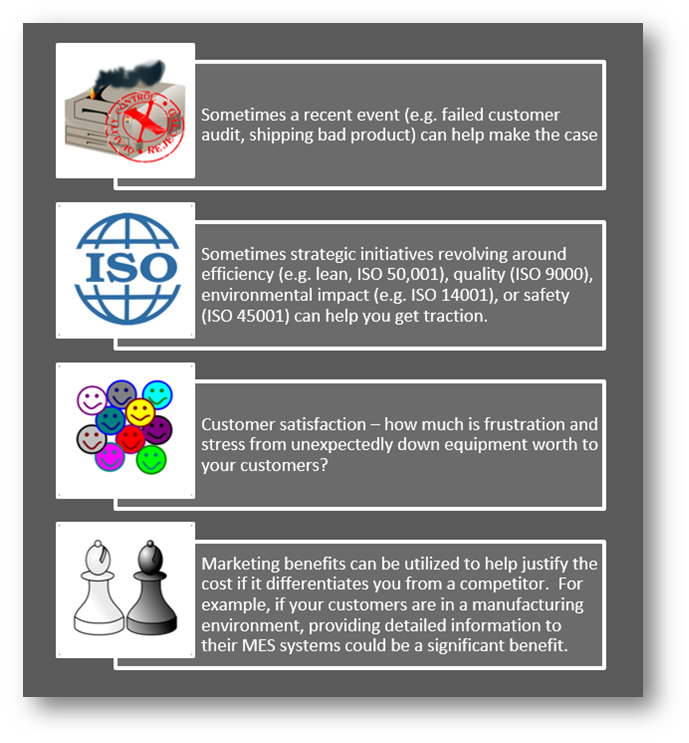
Qualitative Justification:
After reading through the quantitative justification section, you may think that’s your path to success. Not necessarily. If you can justify your case for OCM qualitatively, you may be able to shorten the process to getting your OCM pilot off the ground. Of course, if it makes sense in your scenario, you can always pull both qualitative and quantitative elements to help make your case. Below are some qualitative motivators to consider.
|
KEY POINT: Quantitative & Qualitative justification Don’t limit yourself to trying to come up with a single number for whether or not it makes sense to implement OCM. It may require a combination of quantitative and qualitative elements. |
DECIDING WHAT TO MONITOR
At the end, what you functionally get out of condition monitoring are a series of indicators (faults, alarms, events), that inform you (via a text message, email, or HMI (Human-Machine Interface) to take some sort of action (shut down a piece of equipment immediately, inspect a system further, or start collecting additional data for off-line analysis). These indicators stem from observable physical component properties. Start from both ends, and work your way toward the middle: algorithms.
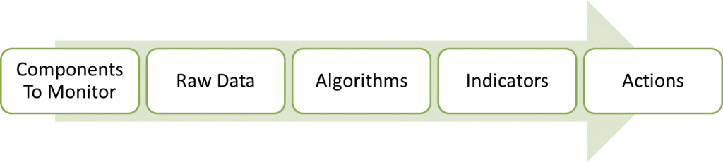
Think about what actions you’d like to be able to take, and work that back into what indicators will be needed. This will drive the sorts of observations that need to be made by the OCM.
The core of the detection algorithms are essentially trying to differentiate (for a given feature) between what you define as a good state and a bad state.

But what if you don’t already have a solid understanding of how to detect a good and bad state for a particular feature? If you’ve not done so already, this starts with a FMECA (Failure Mode, Effects, and Criticality Analysis). This will give you a better sense of each type of failure, its detectability, and its importance. You’ll likely be designing some experiments, instrumenting multiple systems, and collecting a lot of data. This knowledge will be used for subsequent algorithm development.
Reliable Early Detection Indicators (REDI)
Most components that exhibit a physical property that can be sensed, can also be monitored. However, being able to monitor properties does not mean that you can easily detect component faults. All other things being equal, you want to monitor properties that are the earliest indicators of larger issues to come. Monitoring components often involves detecting changes that are:
- Subtle and small
- Really slow or really fast
- Located in electrically noisy environments
We want to find the right balance between minimizing false positives and false negatives. What makes a fault reliably detectable? Three things:
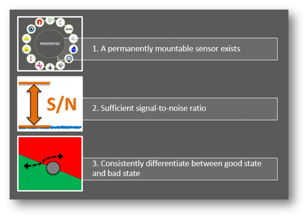
And what do we mean by early indicator? We mean that if this plot is showing performance degradation of a system over time, where we cross from the good state to the bad state at the x-axis, we’d like to know as soon as possible that something is going on.

|
KEY POINT: Reliably Detectable Early Indicators What makes a component/sub-system/system a good candidate for OCM? A reliably detectable early indicator. |
INITIATE A PILOT PROGRAM
A pilot program is your opportunity to prove out what you think you know based on the pieces of the puzzle that you’ve gathered. You’ll need to strike a balance between starting without enough information at hand (totally in the dark), and waiting until you have high confidence that it will work (paralysis by analysis).
The following steps will help you initiate a solid pilot program:
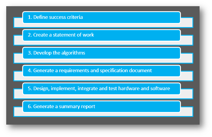
The sections below explain these steps in detail.
Define success criteria – define what success will look like at the end of the pilot program.
This step is critical, since it’s the indicator to your organization that it either makes sense to proceed with another pilot, roll out, or squash the program and go back to the drawing board.
Some potential success criteria might include:
- Able to detect X fault in sub-system Y in order to take action Z, A% of the time under condition B.
- Developed an algorithm that will detect sub-system fault X in order to take action Y, Z% of the time under condition W.
- Compared two sets of sensors and algorithms to determine the best performance and compare compared with our existing manual methods
Create a Statement of Work – help develop a mental model.
A formal SOW is not necessary, but you’ll want to include some basic information to get everyone on the same page. Define the team and team member rolls to encourage individual responsibility and reduce finger pointing. Provide a basic timeline with maybe ~four milestone dates to target. This will keep everyone marching toward the goal. Depending on your scenario, you may or may not need to track cost at this point. Your previously defined success criteria can go into the SOW as well.
Develop the OCM Algorithms –
In this step you need to lay out the likely algorithm structure and data flow for your OCM algorithms. The outputs from this step (depending on complexity of the OCM algorithms) will be a block diagram and/or PC-based code (e.g. C, MATLAB, LabVIEW).
This step may seem a bit out of order, as requirements generation is shown after this step, and it seems like requirements would be needed in order to develop algorithms. This is an iterative aspect of the development process. Your previous FMECA analysis will provide a starting point for indicator requirements, but further refinement will likely be required post algorithm development. You may need to modify requirements revolving around processor capabilities, sensor requirements, or measurement requirements, among others.
Algorithm development approaches may combine:
- Well-established detection methods for certain types of component faults
- Heuristics based on empirical data collection
- Physics-based models of components
You’ll likely be working with real data collected from the system to refine knowledge gained from your FMECA-oriented experiments. The results of this phase will be a set of simulation results. This phase will help you decide whether to:
- Move forward with implementation of the algorithm you developed or
- Go back to the drawing board, possibly looking at other features, fusing multiple properties, or maybe analyzing the utility of some crazy elegant CM algorithm.
Generate a requirements and specification document –
This is the sort of document that (at least at this stage of the game) you want to keep as minimal as possible, while still conveying useful information. This is not a production program, it’s an R&D effort, so there will be many unknowns and several fuzzy specs up front, but that’s okay. Capture what you know and what you believe to be the case.
Where to start:
- Are there any existing requirements from previous analysis work or similar past efforts?
- What existing sensors do you have in place or have you tried on similar systems?
- What existing data do you have to pull from?
- Is there an existing controller within the system under consideration that you can piggyback off of, or do you need to augment with a separate monitoring system?
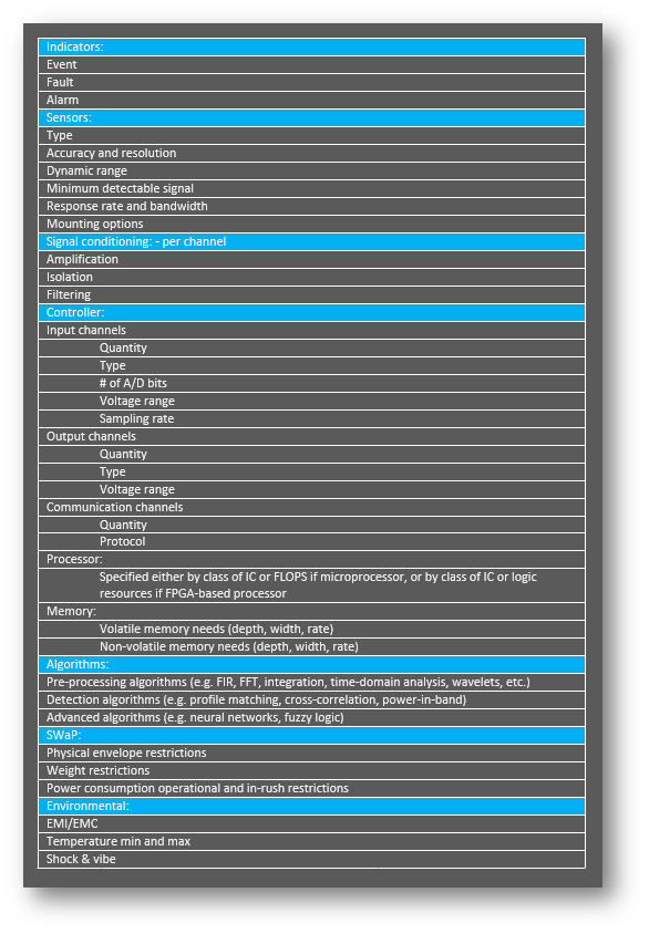
Main requirements and specification sections:
Design, implement, integrate and test hardware and software –
At this point, the engineering flow is very similar to a typical embedded system development project. A couple of important points to highlight are:
- Consider having a solid algorithm analysis and development person as part of the team, as there will be some unexpected head scratchers along the way.
- Depending on the architecture and requirements of your main embedded electronics and the needs of your OCM system, you may be able to combine the base hardware from the embedded controller and just add in the required measurement inputs. This approach can reduce overall system costs.
- You may need to accelerate the fault modes of the system being monitored (similar in concept to HALT/HASS).
If the results from your pilot program are questionable from a statistical validity standpoint, consider one of the following next steps:
- Try enhancing or utilizing alternative CM algorithms (e.g., look for common approaches, connect with a CM algorithm consultant or research center, consider data fusion and heuristics) extract different features, or sense different physical properties.
- Instrument your systems going to the field with data collection capabilities to gather more real-world data over a longer period of time
Generate a summary report –
This step is critical. You need to summarize your findings while everything is fresh in your mind. Add context to the data. Augment with opinions. The report should consist of the following sections:
- Executive summary (written last, and with easy-to-follow visuals)
- Risks and concerns
- Indicator test results
- Indicator test setup
- Unit cost estimates
LOOKING FORWARD AND NEXT STEPS
Making OCM stick: the first step toward scaling and expanding is by preventing a slow fade away into irrelevance. Show its value. Often the value of CM is in having something bad NOT happen. Tying OCM back to its original business case motivators should help. Gather the same metrics that initially suggested OCM and compare them after some long period of time with the pre-OCM results to analyze the expected improvements.
If OCM has been shown to be valuable within a particular product, by all means, start scaling up. Try not to do this as a step function, as new problems will arise that weren’t seen in the pilot program. A phased approach is recommended.
Presumably if you’re reading this white paper, you have interest in the potential that OCM has to offer. More than likely, there is still some uncertainty and unknowns. If you’d like to discuss the specifics of your scenario, feel free to reach out to us.
Comparing Off-The-Shelf To Custom Designs For Industrial Embedded Systems

Comparing Off-The-Shelf to Custom Designs for Industrial Embedded Systems
When creating a new product or adding an incremental improvement to an existing one, engineers need a prototype to test the concept design’s stability, verify key performance metrics, and vet out any bugs.
This paper will address the immediate question that arises: Is it better to buy commercial off-the-shelf (COTS) components or design a completely custom printed circuit board to prototype and build your industrial embedded system?
We’ll discuss:
- COTS vs. Custom: The Dilemma
- Consideration #1: Time and Money
- Consideration #2: Performance and I/O
- Consideration #3: Product Life Cycle
COTS VS. CUSTOM: THE DILEMMA
The types of products we will be considering for this COTS versus Custom debate will contain the following items:
- Programmable controller
- Analog and digital I/O with possible signal conditioning
- Communication ports of some sort
- Possibly a display (i.e., HMI)
- Possibly some packaging
Obviously, the complete product will contain several subsystems, such as sensors, mechanical components, power supplies, and so on. We are going to focus on prototyping and developing the controller and its I/O because, in our experience, the huge number of controller and I/O options are a source of confusion to many people.
Furthermore, from a business perspective, we also want to be cognizant of unit cost of the end-product and the amount of time before we can start selling the product. If the product costs too much or takes too long to develop, we may spend a lot of time and money with unacceptable payback. Hence, the choice of controller will also be driven by business rather than purely technical decisions.
To weigh the pros and cons of the COTS versus Custom approaches, it helps to understand the options along the COTS – Custom spectrum. Ultimately, your goal is to use prototyping to prove out your product design in advance of creating the product that you will put into production and to do it as quickly and efficiently as possible.
The COTS Approach
COTS is an acronym for Commercial-Off-The-Shelf. A COTS prototype is entirely comprised of items that can be ordered from various vendors. Obviously some integration effort and software development are required to create your product concept: if you could buy your product as COTS, you already have a competitor.
Using COTS speeds development of your prototype since you have less to build, can interface to your sensors and actuators with purchasable signal conditioning, and both write and debug your application in a development environment that offers high-level software development tools. The resulting shortened timeline is traded against either high unit cost or high follow-on non-recurring engineering (NRE). The high unit cost happens is you use the prototype design for your end-product. The high NRE happens if you need to convert your COTS design to Custom after you’ve vetted the product design.
The Custom Approach
Building a Custom prototype involves selecting a controller, laying out the circuitry for the I/O signal conditioning and connectivity, writing the application using the tools available for that controller, manufacturing the printed circuit board (PCB), debugging the PCB and app software, and building an enclosure if necessary.
Clearly, this approach takes significantly more effort than the COTS approach before the prototype is available for the intended purpose of evaluating your product idea or upgrade. In our experience, it is common for this effort to take 4 to even 10 times the COTS prototyping effort.
The Hybrid Approach
Your prototype could also be part COTS and part Custom. Such a “Hybrid” approach can offer advantages by combining the increased speed of prototyping with COTS with the reuse of the same hardware and software in both prototype and end-product. By carrying over the effort spent to design and build the prototype and reusing it in the end-product, any NRE is spent once.
The amount of NRE savings as compared to the COTS or Custom approach generally scales with the amount of reuse in software (for the application and drivers) and hardware (for the signal conditioning I/O and connectivity). The ideal situation utilizes the same controller for both prototype and product and couples that with I/O designs that can relatively easily be laid out into a custom I/O PCB that connects with the chosen controller.
Let’s explore these three approaches in more detail by covering three important decision factors that you will face when creating a working prototype and subsequent end-product.
CONSIDERATION #1: Time and Money
Cost is almost always the number one concern for companies when building a product: cost in time and cost in money. In terms of the bottom line, the smaller the costs accrued in prototyping and the faster the new revenue appears, the better the company cash flow position.
Let’s look at some of the largest costs for creating the prototype and end-product.
Custom
Since the Custom path requires that the prototype be developed from scratch, the non-recurring engineering (NRE) effort is very significant right from the start.
This large NRE arises from a development flow similar to the following list.
- A hardware designer must first design the PCB schematic and then layout the board to specification, since the board is being made from scratch.
- After the layout is finished, it can take approximately two weeks to spin the PCB. For expedited delivery times, an additional fee must be paid.
- If a bug is found on the PCB, it will take additional design effort and another two weeks to fabricate the revised board.
- If there are mechanical issues, noise problems, backward connections, or any number of bugs, reworking the hardware can significantly delay the project timeline and considerably increase NRE design costs.
- The software development effort can start in parallel with the design and build of the prototype PCB. However, as all software developers can attest, the real work begins only when the hardware is available and debugging in real-world situations can occur.
- Additional tweaks to the PCB and software can occur during the application development, when the application doesn’t perform as expected.
COTS
COTS solutions tend to have a shorter prototyping phase, since the hardware is ready-to-use out of the box and troubleshooting involves only rewiring, reprogramming, or changing the types and quantities of COTS I/O modules. Hence, most of the effort is in software development, and the NRE in prototyping will be smaller than for the Custom approach.
However, you may need to consider converting your COTS prototype into a Custom design for various reasons such as size, power, unit cost, and maintainability, reasons that are likely driven by market desires that force you to remake your prototype into something that your potential customers will buy.
If you do have to rework your COTS prototype, then the NRE will grow, possibly even larger than the NRE in the Custom approach.
The best argument for staying with COTS for your end-product is when either:
- You are not sure your product idea is viable (you can “fail fast” with COTS)
- You don’t think you will be selling many units (so “low” unit cost is not the main driver of sales) and form factor is not an important sales attribute.
If neither of these reasons apply, the COTS approach will very likely end up converted to a Custom approach and hence as expensive as the Custom route.
Hybrid
Since a Hybrid approach tries to balance the benefits of the COTS and Custom approaches, the NRE can beabout the same for prototyping as the COTS approach. Further, you likely will start with close to the same form, fit, and function as the prototype when it’s time to move to production, leaving total NRE lower than either COTS or Custom.
Specifically, this reuse benefit appears when you select the same COTS embedded controller that would be used in your end-product and coupling it with COTS I/O. This hybrid combination brings you closer to the form factor your end-product needs than would COTS alone. However, note that, if you need some I/O that is not available as COTS, then some Custom I/O will need to be developed and the NRE will increase but only proportionally to the amount of COTS compared to Custom I/O you require.
| Approach | Pros | Cons |
| Custom | Develop for the intended target right from the start. Best if you have a solid idea of your goals, such as an upgrade for an older (possibly obsolete) controller. | Highest initial and total NRE investment due to design and build from scratch. And, if your idea fails, you unfortunately have spent extensive time and money. |
| COTS | Lowest initial NRE. Complete the prototype stage as quickly as possible. Best if you need to do some R&D in order to validate your idea or will have “low” sales volume. Also good if this form factor works for your end-product. | If the COTS hardware needs to be reworked on a different platform to build the end-product, you will spend significant NRE on the end-product design and development. |
| Hybrid | “Low” to “medium” initial and total NRE. Fastest development. COTS controller enables the software to be developed on the same controller used in the end-product. I/O modules of acceptable form factor or access to I/O designs allow the end-product to be designed quickly. | If the prototype I/O form factor is not suitable, you will either need to design custom I/O or rework the prototyping vendor I/O boards. Look for vendors that have open or licensed schematics so the I/O layout can be moved to alternate forms. |
CONSIDERATION #2: Performance and I/O
Your prototype and end-product need to be capable of reacting to inputs, processing data, crunching algorithms, and updating outputs as quickly as needed for your product’s application. Achieving this throughput requires both a controller powerful enough to handle all the tasks and I/O with enough bandwidth, precision, accuracy, and damage protection from the outside world.
The controller market is very mature and offers a broad range of products, from tiny, low-power, very simple microcontrollers to high-speed, fully-featured 32-bit computers. The on-chip peripherals can include:
- Memory (EEPROM, RAM, and Flash)
- Communications (CAN, Ethernet, RF, USB, I2C, SPI, and UART)
- Timers/counters
- PWM channels
- Encoder interfaces
- A/D convertors
- Graphical and touchscreen interfaces
- FPGA
Besides the controller, analog and digital I/O capabilities will be needed. Not only does the controller need to support the appropriate channel count and speeds, you will need signal conditioning between the controller chip and external sensors and actuators.
Also, you may wish to consider an FPGA to offload time-critical acquisition and processing from the controller. A Field Programmable Gate Array (FPGA) is a special integrated circuit consisting of logic blocks with interconnects that can be programmatically “rewired” via VHDL (VHSIC Hardware Description Language) to create different complex applications. Moreover, FPGAs can execute algorithms in parallel with no task switching.
Often, we find that domain experts, while expert in their field, have little experience with embedded technology, and they can be overwhelmed with so many options when trying to choose an embedded controller and I/O for their product concept. Let’s review some of these options.
Custom
Embedded controller companies offer many reference designs that can be leveraged for use in your prototyping circuitry. Many of these reference designs use support ICs made by the same company that makes the controller, so you can gain the benefit of additional components being from a one-stop-shop.
To assist, many companies offer pre-assembled development kits (also called eval boards) that have the controller and a number of features already implemented to help streamline prototyping for certain types of applications. Keep in mind that these starter boards are created as demo versions of the manufacturers’ product, and will often still require heavy customization to become prototype-ready.
For software development, controller companies often provide in-house C and assembler compilers, along with many third-party vendor toolsets. Any FPGA component is usually programmed in VHDL. The application software typically runs on either Linux or some real-time operating system (RTOS). Several RTOS choices are available, including real-time versions of Linux.
For the I/O in a custom prototype, the channel granularity matches the requirements precisely, and you pay only for the necessary features, thus minimizing price per unit of your product. Furthermore, when the system requires support for special sensors and signals, signal conditioning, or signal connections that are not readily or inexpensively available as COTS, or may require many intermediate COTS products, then building a custom solution is more reasonable than buying a COTS solution. It will likely be more straightforward to build the prototype from ground up so that the specifications – such as noise performance, voltage levels, or dynamic range – are not compromised by the availability of COTS products on the market and instead are exactly tailored and optimized to the product’s needs.
| Additional Information: As an example of the advantages of utilizing a one-stop-shop, Microchip (www.microchip.com/) has a very broad set of pre-coded libraries that simplifies the use of their on-chip peripherals, such as software stacks for TCP/IP and Bluetooth, as well as algorithms for DSP-based products, graphics libraries for displays, and much more. This example serves as motivation for you to explore options. |
COTS
With the COTS approach, you will want to consider a COTS embedded controller that is also ready to accept I/O modules without the need for any customization. Also called Embedded CPUs or Embedded PCs, these controllers will be plug-and-play compatible with COTS I/O modules. Some examples of such systems are the National Instruments CompactRIO and systems based on single board computers utilizing PCI plug-ins for the I/O, offered by such vendors as ADLINK, Advantech, Arduino, Raspberry Pi, and many others. These systems often run a version of Linux for the operating system and some are real-time.
With all these COTS components readily available for purchase, the COTS solution is generally more adaptable to change and the COTS solution can usually be easily modified during multiple prototype revisions.
For instance, the prototype may need just one current input channel, but the COTS supplier only sells modules with four current inputs each. The downside is that three extra channels were purchased and may never be used, taking up both space and budget. The upside is that if the prototype does need more than one current input, the additional channels or modules are immediately available for use and little time is lost. Also, the extra I/O can come in handy for monitoring or troubleshooting an issue on the prototype.
As another example, if the prototype unexpectedly needs an analog output, the COTS supplier likely already has a module for sale. Again, the downside is that additional budget and space have been consumed, but the upside is that a solution was readily and rather inexpensively available.
However, COTS analog or digital I/O boards may not offer adequate connection schemes because of signal speed, channel-to-channel isolation, signal conditioning, or connector requirements. In those cases, custom circuitry and hardware may need to be built in order to add special functionality to COTS systems, which can increase time and cost.
| Additional Information: Some examples of COTS systems are the National Instruments CompactRIO (www.ni.com) and systems based on single board computers utilizing PCI plug-ins for the I/O, offered by such vendors as ADLINK (www.adlinktech.com), Advantech (www.advantech.com), the industrial flavors of Arduino (www.arduino.cc) and Raspberry Pi (www.raspberrypi.com), and many others. These examples should serve as motivation for you to explore options. |
Hybrid
The hybrid approach can utilize both a COTS embedded controller and pre-developed COTS I/O. Connecting this COTS hardware into a prototype system is certainly simpler than the Custom approach and is only slightly harder than offered by the COTS approach. The benefit of the Hybrid approach stems from the ability to develop the prototype close to the same timeline as the COTS prototype and minimal post-prototype customization since so much of the COTS hardware can be reused.
It is important to note that ease of rework to convert the prototype into a ready-to-sell product implies either that 1) the COTS I/O is directly suitable for your product or 2) you have access to the COTS I/O hardware designs so that you can (or the supplier of the COTS I/O will) re-layout only the necessary I/O components into your own specialized I/O board.
| Additional Information: Examples of vendors that offer such a hybrid approach are those that are built on the PC104 standard, such as WinSystems (www.winsystems.com) and RTD Embedded Technologies (www.rtd.com). And see www.pc104.com for a longer list of PC104 suppliers. Also look at systems based on the National Instruments RIO standard, such as the VERDI platform from Viewpoint Systems. |
| Approach | Pros | Cons |
| Custom | Optimally chosen components deliver only the performance and I/O that you need. | All the components have to be made from scratch and to work properly together. |
| COTS | Wide choice of options. | The chosen configuration likely will have more performance capability and I/O than you actually need. |
| Hybrid | Balance between smaller choice of performance options than either Custom or COTS and optimal I/O selections. | If the I/O available for prototyping is insufficient or overly capable, an NRE effort is needed, but the outcome is an optimal selection of just the I/O you need. |
CONSIDERATION 3: Product Life Cycle
Selling a product is the ultimate goal. Consequently, consideration must be given to the number of units you expect to sell and the timeframe in which they will sell: do you have a large backlog of customers anxiously waiting to purchase your product or will the product sales ramp over several years? We want to understand the impact of NRE and future product updates on the unit costs of the product over the several years it will be sold, simply because you will want to recoup your NRE investment and quickly.
Let’s explore the COTS versus Custom options to understand the impact of sales on the production life cycle. For the purposes of scale, let’s say that “high” volume sales mean anything larger than 50 units per year. In our experience, the crossover of unit cost between the various COTS, Custom, and Hybrid approaches is often between 10 and 100 units (total, not per year).
Custom
If you know or suspect that you will have “high” volume sales, then starting with a Custom approach is going to give you the lowest unit cost as quickly as possible. The NRE will be highest for this approach, due to all the custom development work and any possible certifications you might need (such as a CE Mark), but the Cost Of Goods Sold (COGS) will be as small as possible. Spreading the NRE costs across each unit sold for this “high” volume situation allows you to keep unit pricing low because you’ll recover your NRE “quickly”.
However, if you do not expect to have “high volume” sales, then this Custom approach is going to make the unit price high for a “long” time. Unless you have a strong reason to follow this approach, such as size or power constraints that your customers demand, use one of the other approaches.
An important benefit of the Custom approach is that longer term modifications, warranty support, and parts life cycle management will be in your direct control, since you have access to all the designs and parts lists in your product build.
COTS
The COTS approach is best suited to “low” volume sales, especially if the customer places minimal constraints on the product design, such as size and power. For example, if your product already has a large enclosure for motor controllers and power supplies, an embedded PC or embedded controller can be very effective. Furthermore, if controller and I/O are a small fraction of the cost for all the remaining components in your product, then unit costs for the embedded system may be less important than reducing costs elsewhere, and you may be able to tolerate using COTS, even for “high” volume sales.
Furthermore, if you are using these initial unit sales as a way to build understanding of your customers through the early adopters of your product, then the COTS approach is especially beneficial, since you can make an updated version quickly compared to the other approaches discussed in this paper.
The life cycle management of a COTS approach offers the advantage of pushing the management of the parts life cycle onto the supplier of the COTS components. Warranty handling can be simplified when using COTS, since the supplier takes much of the risk in product failures. Worldwide support networks often exist for the larger COTS suppliers, and your customer halfway around the world can get a replacement part delivered and possibly installed by the supplier instead of needing to ship parts around the world and talking (or traveling) to the customer for the replacement procedure.
Hybrid
The Hybrid approach combines the benefits of a “low” unit COGS with a “medium” NRE to enable a rapid time to market with reasonably “low” unit costs. This benefit appears because the COTS controller is merged with some combination of COTS and Custom I/O. Thus, this approach can be effective for both “low” and “high” volume sales.
Longer term modifications, warranty support, and parts life cycle management are partly in your control and partly controlled by the vendor of your COTS components. In our experience, your custom parts are often tailored to your product in ways that would make a COTS approach too expensive or even not available. Often, these custom tailored parts are a differentiator for your product (easier field connections, higher signal to noise, etc.), and you would prefer to keep life cycle control over these custom parts, rather than turn over that life cycle management to a COTS supplier. Thus, the Hybrid approach places life cycle management of specific components with the most appropriate people.
| Approach | Pros | Cons |
| Custom | Best for highest volume sales or when needing lowest unit costs. Offers most control over changes to product components, since you are in control of more aspects than any other approach. | You have to manage the entire life cycle yourself from warranty returns to end-of-life components. |
| COTS | Highest leverage of vendors to help manage the product life cycle, since most of the product is COTS. | Least control over component obsolescence. Part can go obsolete too late for you to react. |
| Hybrid | Balance between vendor and your management of component life cycle. Since I/O is often your design, you keep control over your IP and leave controller life cycle management to a COTS vendor. | The COTS controller vendor may obsolete the controller with little time for you to react. |
Summary
The choice between using Custom components for prototyping and product build versus COTS is balanced with a Hybrid approach that utilizes a COTS controller with as much COTS I/O as possible but in the same form factor used in your end-product. The initial NRE for Custom is highest, but COTS may end up having almost as high an NRE too if you have to redesign COTS into a custom solution after prototyping for reasons of unusable form factor, excessive unit cost, or concerns about lack of control in the product life cycle. The Hybrid approach balances many of the NRE costs and life cycle issues by letting you focus on your IP in the form of software and I/O while letting a COTS vendor manage the controller and its standard peripherals.
Next Steps
If you want some help making a decision for your industrial embedded need, you can reach out for an industrial embedded consultation.
If you’re deep into learning mode, check out these resources:
- Outsourcing Industrial Embedded System Development Guide
- Industrial Embedded System Design Services – How much does it cost to prototype?
- LabVIEW Industrial Automation Guide
- Industrial Embedded Case Studies
- LabVIEW Uses – What is LabVIEW used for? 4 Purposes
- Use Of Embedded Systems in Industrial Automation
Is Condition Monitoring Right for You?

Is condition monitoring right for you?
Making your systems smarter with automated condition monitoring
- Have you ever had one of your machines, systems or assets go down without warning?
- Have you ever wondered if you could minimize these headaches?
- Are you innovative?
Condition monitoring may be able to help solve your problems.
Introduction
Condition monitoring of machines and systems has been around in some form for several decades. Early forms of monitoring and analysis were manually done by humans. A person would take measurements (e.g. various probes) or inspect the system with their available sensors (e.g. eyes, ears, hands). Sometimes this monitoring took place on periodic intervals, and other times only after a significant problem had occurred within the system. The evolution of processing capabilities along with the proliferation of various sensor technologies has historically allowed very expensive and mission-critical systems (e.g. military aircraft) to be monitored in conjunction with regular system operation. Given the constant introduction of new technology and lower price of entry, this technology can and will be implemented in more and more systems.
In this whitepaper we will provide some basic answers to the following questions:
- When should I consider implementing condition monitoring?
- What types of physical properties can be sensed?
- What types of components can be monitored?
- What types of information can be produced?
- How do I translate the information into decisions?
This last item is where benefits come into play.
The role of humans in the monitoring process is evolving from direct probing and measurement to higher level analysis and specification of techniques and requirements. As in many cases in our ever-advancing society, humans will likely continue to lean on machines to do the more menial, repetitive, error prone, and dangerous tasks, while humans focus on more complex and creative sorts of tasks.
As systems gain intelligence, it will become more and more important to build in safety mechanisms and feedback loops. It is imperative that these tightly or loosely coupled feedback loops don’t trigger catastrophic events like a flash crash resulting from an unstable system.
When to consider condition monitoring
Typical candidates for condition monitoring include large industrial machines, equipment, and structures. More specifically, this can be broken into two main environments:
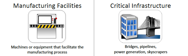
From a product or system lifecycle perspective, similar to typical product development, there are three main points in which condition monitoring may be injected:
- To instrument existing systems to collect data to justify incorporation into future designs
- To augment existing systems
- To build monitoring into new designs
More generally, any system that meets the desired return-on-investment (ROI) is a candidate for condition monitoring. ROI can and should attempt to account for straightforward factors such as direct downtime costs, as well as more complex factors, such as customer satisfaction, employee retention, and environmental impact.
There are three primary reasons to consider condition monitoring:
- Reduced downtime (which increases throughput, profit, and staff and customer satisfaction)
- Increased safety (which drives down insurance costs and minimizes lawsuits)
- Improved environmental impact (by reducing manufacturing waste or preventing impending structural failures)
The stakeholders for considering condition monitoring may include some of the roles outlined in the below diagram:

Making the choice to incorporate condition monitoring is, at a high level, similar to other decisions made in the business environment. However, there may be more indirect or complex costs to consider in the process. Consider the following direct and indirect costs to help determine the ROI for a particular system. Understanding loaded labor rates, cost-of-goods-sold (COGS), and various strategic goals (e.g. employee retention, customer satisfaction, environmental initiatives) will prove useful during this exercise.
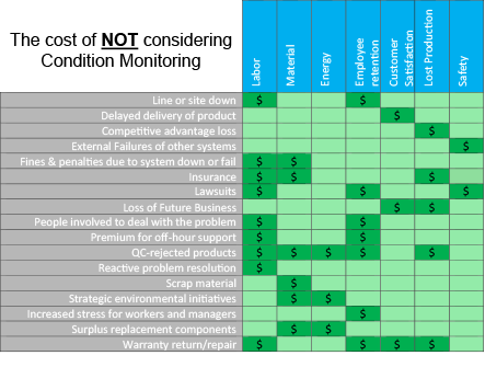
TAKE AWAY: WHEN TO CONSIDER CONDITION MONITORING
Does ROI justify it? The ROI should consider both direct and indirect costs, stemming from complex factors such as safety, employee retention, customer satisfaction, and competitive advantage.
What information can be sensed
In order to determine the condition of any aspect of a system, it is necessary to first measure some physical property. It is often desirable to sense information that can act as a leading indicator before the system becomes inoperable. There are numerous types of sensors, each of which measures a physical property in a particular manner, and then transduces that measurement into an electrical signal that can be processed by electronic systems.
Here is a list of some physical properties that can be sensed, along with some corresponding sensors:
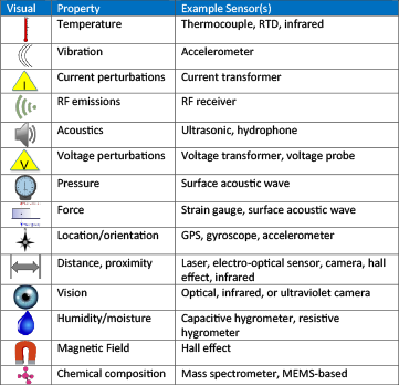
Many sensors are available in miniaturized form factors — or will be over the coming years — through the utilization of MEMS technology, allowing for implantation of more and more sensing devices.
Important specifications for sensor selection include:
- Accuracy and resolution
- Dynamic range
- Minimum detectable signal
- Response rate and bandwidth
Other requirements to consider may include:
- Environmental specifications (e.g. temperature, shock, vibration)
- Size, weight, and power (SWaP)
- Mounting options
- EMI/EMC compliance
Interfacing to the sensor to get accurate digital data to a processor can be quite involved and require significant expertise. Transduced signals often need signal conditioning (e.g. amplification, filtering), and then sampling, processing, alignment, and formatting prior to being utilized by the main monitoring algorithms.
Calibration is an important topic, but will not be discussed in this paper as it is a more in-depth technical discussion.
TAKE AWAY: INFORMATION TO SENSE
Nearly any physical property can be sensed. The challenge that condition monitoring can address is accuracy in sensing and in maintaining the integrity of that information.
What components can be monitored
Most components that exhibit a physical property that can be sensed can also be monitored. This is straightforward as a high-level concept, but proper implementation is not always simple. In addition, just because component properties can be monitored, does not mean that component anomalies can easily be detected.
So which components should be monitored? The most relevant components to monitor are often those that act as the best early indicators of larger issues to come. Therefore, a solid understanding of the failure modes is important.
If you don’t know which components are good candidates to be monitored, a common technique is to instrument up a system with more sensors than are needed, collect a lot of data, and analyze the data to find the best indicators. Often the shape of a signal can be more important than the value. Time is another dimension in data collection that is implicit, but very useful. Think about short-duration waveforms and long-duration trending.
This list contains example components that are possible candidates for monitoring:
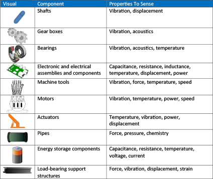
The best indicators aren’t always the easiest components to monitor. Monitoring components often involves detecting changes that are:
- Subtle and small
- Really slow or really fast
- Located in electrically noisy environment, resulting in low signal-to-noise ratio (SNR)
Additionally, the sensor may be challenging to mount because of:
- Rotating components
- A mounting location that blocks machine operation
- A challenging mounting surface for long-term mounting
TAKE AWAY: COMPONENTS TO MONITOR
Component monitoring selection must take into consideration the ability to detect changes, the ability to detect them early, and the ability to mount the sensor.
What information can be produced
Information is produced through various signal and data processing algorithms and techniques. Processing may consist of many forms of heuristic algorithms, utilizing multi-sensor homogenous and heterogeneous data fusion, M-of-N processing, rapid change detection, profile matching, order analysis, cross-correlation with known-good data, and time- and frequency-domain thresholds and windowing. Beyond this, there are several more advanced processing techniques, including those within the realm of machine learning and related domains of processing (e.g. IMS – Watchdog Agent).
In order to perform the desired signal and data processing, it is very important to choose a platform with the right processing capabilities. FPGAs, GPGPUs, DSPs and μPs are common processor categories. Appropriate selection depends largely on the algorithms utilized. Questions revolving around the following will help drive the decision process:
- Timing determinism and response time
- The type of operations (floating point vs. fixed point, trigonometry, divides)
- Parallel vs. sequential processing
- Interface and communication with other systems
Heterogeneous platforms (e.g. those with a combination of multiple types of processing elements such as an FPGA with a μP) are becoming more common and allow for the strengths of both platforms. In fact, some platforms are utilizing system-on-chip (SoC) technologies that combine an FPGA with a μP. A few examples of heterogeneous processing platforms include:
Various forms of detection algorithms can produce status information, warning flags, and alerts to indicate that some component of the system is outside of the specified bounds.
In a few, very well-understood cases, Remaining Useful Life (RUL) can predict — with particular confidence intervals — how much time a particular component, sub-system, or system has left before action must be taken.
TAKE AWAY: INFORMATION
Signal and data processing can range from simplistic to very sophisticated. The algorithms chosen vary widely based on objectives, level of understanding of the problem, and project funding.
What decisions can be made?
At this point, depending on the confidence level of the information provided by the condition monitoring system, a decision may be made to either:
- Investigate further
- Stop a machine to prevent destruction
- Halt production, construction, vehicle or rail traffic, or shut off valves in pipes, depending on the type of system being monitored
Currently most decisions are simple go/no-go, intended to reduce the probability of more severe events occurring, or to sound an alert that a serious event is occurring or had occurred.
Condition monitoring is an area of active research for the early detection of subtle effects. No one should base their use of condition monitoring on these subtle effects. Without collecting and saving the data, detecting these subtle effects will never be available. Start collecting data now!
If monitoring is being performed for data collection purposes to determine what to monitor on future designs, be sure the information is well-indexed and contains appropriate metadata so that context can be determined.
Optimization of facility or site operations is another important use of condition monitoring. The resulting information can be utilized to help improve efficiency in areas such as electrical power consumption and machine maintenance.
TAKE AWAY: DECISION MAKING
Ultimately condition monitoring can help you decide when to take action regarding a particular system and which components should be modified in future designs. If you are new to condition monitoring, start collecting data now!
Looking forward and next steps
As our systems become smarter, more automated, and more interconnected, it will become more and more important to understand the overall condition of the system in order to make better decisions. Cyber-physical systems will become more intertwined with our lives and productivity.
To develop a complete solution, it is important to factor in considerations that arise for many electronic systems: signal and component interfacing, enclosures and housings, SWaP, and lifecycle support. A solid engineering development process is essential and should involve requirements definition, system architecture, electronics design, software development, unit test, system integration and test. A knowledge base within the domains of systems engineering, electronics engineering, and software development are important.
As a result of implementing condition monitoring, benefits such as increased throughput, cost reductions, happy bosses, happy workers, happy customers, and environmental conservation can be achieved. These factors can improve the health of your company in the long run. If you have a condition monitoring challenge that your curious how we’d tackle, feel free to reach out to us.
We’ve helped teams at some of the world’s most innovative companies