Testing Digital Imaging Subsystems via Emulation
![]()
This article discusses an emulation platform built from COTS-based hardware for testing digital imaging systems. For a comprehensive coverage of typical tests, the main goals of such a platform are:
- Useful for design and development
- Adaptable for production testing
- Modular so that any customization effort is minimized
- Easy integration into existing test flows
We wrote this article to share our experiences with creating and deploying such a platform (AEDIS) over the past 10+ years for companies that might be considering an in-house development effort and would be interested in learning what is possible with COTS equipment. Being an engineering firm, i.e., not a marketing firm, the name AEDIS naturally arose from an acronym for An Emulator for Digital Imaging Systems.
This article focuses mainly on the testing done during the design and development of a digital imaging system, not manufacturing. These systems tend to be low-volume and high-performance and the design effort often has multiple subsystems being developed in parallel. Yet, when a product goes into production, it is efficient to have a test system based on this design tester since test features can be replicated more easily than starting from scratch. Plus, the COTS aspects help manage life cycle for both its software and hardware components.
Note that digital imaging systems are often termed EO/IR systems in military and law enforcement applications due to the required capability of digitizing both visible and infrared images.
The digital imaging system components applicable to this article are the focal plane array (FPA), with its associated readout integrated circuit (ROIC), and the electronics connected to the FPA that manage the command and response messaging and the data transfer to the downstream image formation and processing.
Figure 1 outlines the parts of an imaging system which a digital imaging system test platform should cover:
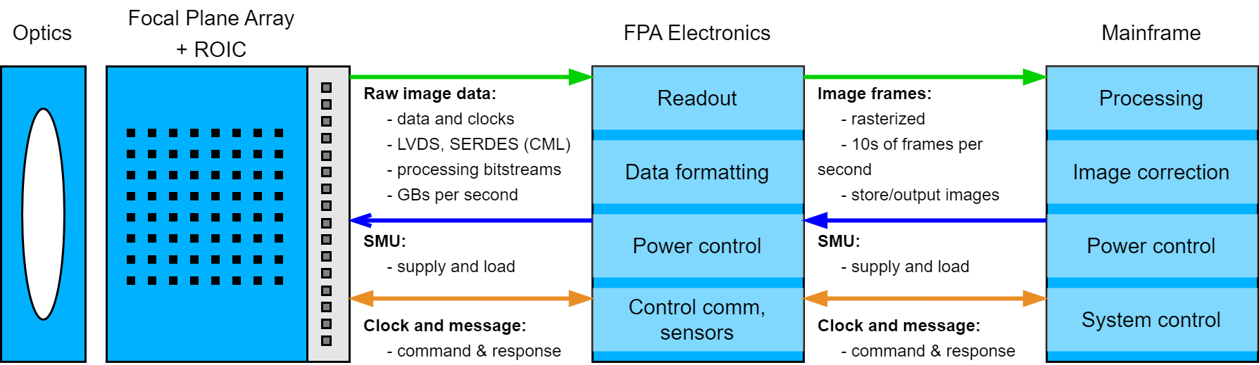
Figure 1 - System schematic of a digital imaging system
Why use emulation in testing
As seen in Figure 1, digital imaging systems are complex with many subsystems each of which usually follow separate but flanking design paths to meet the requirements for image capture and for interfacing adjacent subsystems.
Testing the overall system is done by partitioning the tests such that each subsystem has its own test set. Once confirmation of each subsystem’s functionality is complete, integration into the whole will proceed more efficiently.
In our experience, by far the largest use cases for emulating digital imaging system are in the leftmost two blocks (not including the optics). A smaller set of use cases we seen emulates digital data used in the mainframe for handling data that links to the “home base”.
- Emulating the FPA electronics to test the FPA/ROIC,
- Emulating the FPA/ROIC to test the FPA electronics, and
- Emulating the digital data handled by the Mainframe.
This partitioning approach allows these subsystems to be developed in parallel. The same parallel approach applies to the mainframe, of course, and the COTS system design discussed here is also amenable to testing this subsystem.
And, for the sake of terminology, we call a system that generates signals for output a “pitch” system and a system that acquire signals as input a “catch” system.
Comparison of COTS with FPGA protoboards
Emulators have been utilized for many years for product design testing. However, test developers often utilize protoboards for highspeed FPGA acquisition and initial pre-processing rather than COTS hardware. It’s worth comparing this approach to a COTS-based platform.
Protoboards offer the latest and highest performance technology but they come with the cost of a challenging development environment and integration path and a generally short lifecycle for the protoboards when compared with COTS equipment. These hurdles often muddle the benefits and increase the risk of using a protoboard approach. In addition, these protoboards and the tools used to configure them become obsolete faster than COTS equipment, since the protoboard manufacturers are incentivized to move onto the next version of FPGAs, while COTS suppliers want to stabilize on a design for years to recoup design costs. Furthermore, emulators based on FPGA proto-boards and/or many of the same components as the digital imaging system themselves leads to an engineering effort similar in scope for creating the emulator. However, by having a flexible emulation system based on COTS hardware and software, the costs and schedules for the development of the systems are reduced, sometimes drastically.
A test system based on COTS hardware and pre-developed software that is designed with a reusable, modular structure is a suitable alternative if it can meet bit rates and storage needs. A good choice for the COTS hardware uses FPGAs based on NI’s FlexRIO modules mounted into a PXIe chassis with a high-throughput backplane. Furthermore, multiple FlexRIOs synchronized to the same clock results in large channel count capabilities.
Our experience is that some 80+% of typical requirements can be supported with this modular design, sometimes even as much as 100%. Any remaining portions specific to unique needs should be customizable to meet the digital imaging system requirements. Specifically, software and hardware should be configurable via:
- Software should be configurable through configuration and test scripts.
- Hardware connections should be configurable via interconnects based around common signal types such as LVDS and SERDES (CML).
When we started implementing such system over 10 years ago, the performance and modularity was more limited due to less standardization in the electronics used by the industry and by the capabilities of the COTS FPGAs. Customization consumed around 60+% in the early days.
For the EO/IR systems and other digital imaging systems we’ve encountered, we’ve found that the COTS equipment available today is capable, cost effective, and time saving. And both software and hardware configurability can be managed via configurations “on the edge” to give an actual 80+% coverage.
Furthermore, the modularity of the COTS solution means that a system designed for a 1K FPA is expandable to a 10K FPA with the addition of “more of same” hardware while maintaining the same software interface. This modularity adds to the benefits of COTS over protoboard-based purely customized systems.
We have also concluded that, for the purpose of testing these digital emulators for our clients, we use a “mirror image” AEDIS system. For example, if building a pitch system, testing that pitch system with a “mirror image” catch system is a huge time-saver. The large number of signals and clocks in a typical digital imaging system make using something like a logic analyzer or high-speed digital recorder a less economical and schedule-efficient method.
The rest of this article will focus on the COTS approach. Details will be discussed regarding important requirements, tweaking with minor customization, and some associated “gotchas” to consider for a digital imaging system test system.
Common Requirements for a Digital Imaging System Emulator
Generally, the set of needs for the combination of pitch and catch emulators include the following basic features:
- Support for industry standard signal logic levels such as LVDS and CML
- Processing bit streams to extract (or create) pixels, lines, and frames
- Real-time organization of complex data payloads into meaningful datasets
- Incorporation of possibly proprietary data processing, such as encryption or packing, into the bit stream(s)
- Ability to acquire and store GBs of data at very high rates (e.g., GB/s across multiple simultaneous and synchronized bit streams)
- Ability to generate, either from a file or real-time algorithm, post-process into appropriate packets and data streams, GBs of data at very high rates (e.g., GB/s across multiple simultaneous and synchronized data streams)
- Combine COTS and customizable hardware to accommodate user’s end-product chipsets and cabling connections
- Incorporate adjustable electronics power supply and loads via source/measure units (SMUs)
- Interfacing with Test Program Set equipment and software
- Ability to inject noise and faults in real-time
The backbone of such an emulator is the high-speed and high-throughput capability for generation and acquisition. However, it is important to recognize that system emulation is most often effective only when one or more of these other features are available.
The high-level diagram in Figure 2 illustrates a use case for an emulator used to test the FPA/ROIC. This configuration is the “catch” system. On the left side, the FPA/ROIC device under test (DUT) is connected to the test system through an Interface Test Adaptor (ITA). On the right side, the test platform consists of breakout hardware which connects to NI’s FlexRIO modules. The test platform software manages the collection of the image data from the DUT and the commands sent to and received from the DUT. A REST-based Application Programming Interface (API) is a standard option for the test engineer to integrate the test platform into an external test application for overall automation and interfacing to data storage. Other API methods are possible with customization.
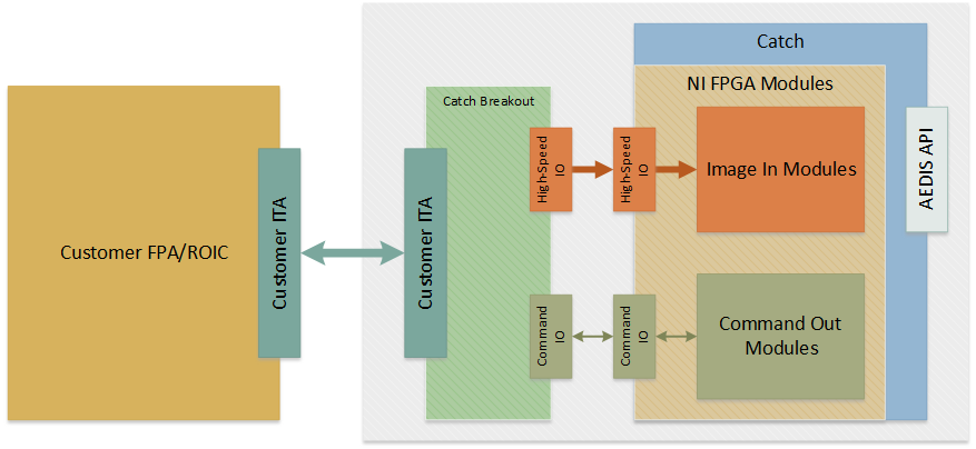
Figure 2 – Schematic for “catch” system for testing the FPA/ROIC
The needs of a breakout ITA connector are discussed in more detail later in this article.
When testing the FPA electronics, the reverse configuration is used as shown in Figure 3. This configuration is the “pitch” system. Now, on the right side, the FPA electronic DUT is connected to the test platform, on the left. The blocks in the pitch schematic match one-for-one the blocks in the catch schematic, illustrating the mirror symmetry in the pitch and catch systems.
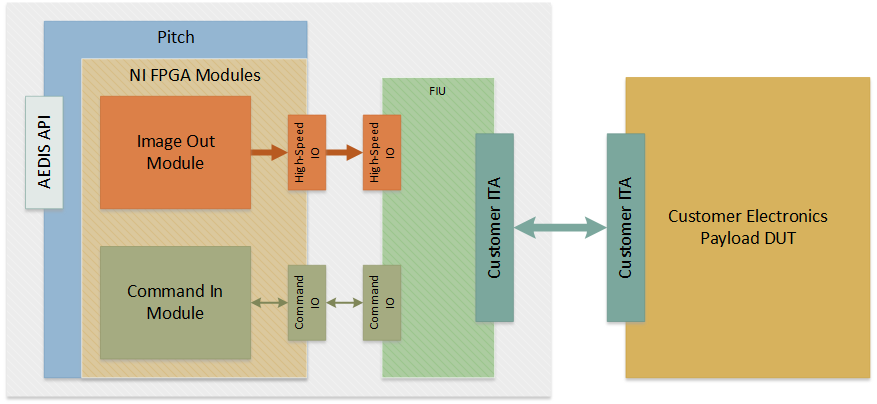
Figure 3 - Schematic for “pitch” system for testing the FPA electronics
This symmetry is a huge benefit for the development of the COTS pitch and catch testers since many of the same hardware components for the catch system can be repurposed in the pitch system and vice versa. The same reuse applies to much of the software modules.
Another benefit from this symmetry is that the pitch and catch systems can test each other when connected “back-to-back”. Such verification testing can check wiring, channel configuration, signal integrity (through test points built on the breakout I/O modules), and handling of image and commands.
Some Details about a COTS Platform
For digital imaging system emulation, the basic features, listed in the section above on requirements, translate into the following design goals for the COTS hardware and software tools for the emulator platform:
- FPGA for on-the-fly processing in-line with the bit streams.
- FPGA module connected to a fast backplane for data transfers to RAM, RAID, and CPU.
- COTS and custom front-end hardware for the module(s) for cabling to the digital imaging system.
- COTS front-end when COTS cabling can connect to the system.
- Custom front-end to connect actual product cables and/or product chipsets to connect the COTS hardware.
- Connect to signals of various logic levels. Preferred choices are LVDS and CML.
- COTS PC and chassis to house the FPGA module(s) with connection to any necessary RAM and RAID device(s). This PC needs a fast backplane, such as a PXIe multi-lane backplane.
- COTS supports hardware such as a timing and synchronization module and an SMU.
- Pitch software:
- Stream pre-defined images from RAID, memory, and high-speed sources (i.e. 10 GbE)
- Precisely synchronize signal outputs across FPGA modules
- Modify pixels on-the-fly
- Mimic ROIC read out patterns
- Send commands and receive status
- Control signals to ROIC
- Manage power conditions
- Catch software:
- Handle channel delays and pattern lock
- Raw or depacketized data streams
- Pixel mapping
- Arbitrary image size
- Capture to RAID, memory, and high-speed connection
- Basic image analysis
- General software:
- Command and response management for both pitch and catch
- API to manage system as an instrument within a complete test set
- Software configurability:
- User-editable JSON configuration files for image definition and bits streams, including channel skew adjustments
- User-editable JSON recipe file to control test flow for unique and repeatable test runs
- Application interface to provide a user with configuration and status
- Open application sources to enable a user to add customized features, at the FPGA layer up to the application layer.
A high-level diagram of a pitch system is shown in Figure 4, and a high-level diagram of a catch system is shown in Figure 5.
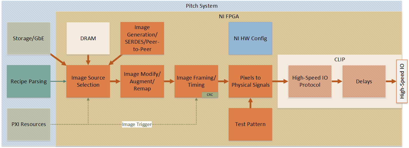
Figure 4 -High-level system diagram for pitch system
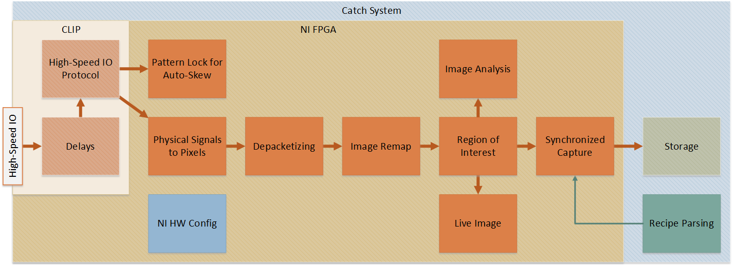
Figure 5 - High-level system diagram for catch system
When is COTS not sufficient?
Modularity of a COTS system is often a hallmark benefit. A test platform designed around modularity and flexibility will reduce risk, cost, and schedule over a customized test platform. Also, a modular approach helps with the life cycle management of both the emulator’s hardware and software since the COTS modular components can be adapted or changed as newer and more capable digital imaging systems are created.
While a significant amount of flexibility can be supported in a COTS platform through configuration files, such as differing numbers of data taps and clocks for the FPA/ROIC, sometimes unique requirements necessitate customization beyond what a COTS platform might offer out of the box. There are two areas in which we have seen the most need for customization.
First, the need to perform specialized customized bit stream processing which is outside the scope of the adjustments we can make in the image capture (or generation) scripting configuration file. In these cases, the FPGA on the NI FlexRIO module enable support of these specialized cases by reworking some, usually small, portion of the FPGA logic.
Second, we often see a need to connect to the specific connectors used on the digital imaging system, and thus the physical and electrical connections of the COTS system must match that of the DUT. We manage this need by developing a custom breakout ITA designed to connect DUT I/O to the NI FlexRIO(s). Furthermore, if the NI FlexRIO or any COTS signal conditioners already designed can’t accommodate the DUT’s unique signal levels or impedances, custom signal conditioning modules can be developed.