Industrial Embedded Monitoring & Control for the Energy/Power Industry

How we can help: our capabilities & expertise
Our expertise in the energy/power industry focuses on monitoring and control of systems and sub-systems.
We’ve got experience with power measurements and power conversion (AC/DC, DC/DC, AC/AC, DC/AC) and motor control & monitoring.

Want more proof points? Check out these case studies:

Industrial Monitoring for a Harsh Environment
Industrial Monitoring for a Harsh Environment
Developing an industrial monitoring system for ultrasound-based sensing in a harsh environment
Client – Energy Research Lab
Challenge
Our client was experiencing problems making temperature measurements in a hostile, irradiated environment. Traditional temperature sensors don’t last long in this environment, so our client was developing a sensor designed for these conditions.
Special equipment is required to drive this sensor. It’s an active sensor requiring an ultrasound pulser/receiver (P/R) and high-speed digitizer to make it function.
The prior attempt the client made at using an original set of special equipment was having reliability and connectivity issues. This reduced reliability was of critical concern due to the requirement for the sensor to operate for years without downtime.
In addition, the existing application was incapable of displaying live data and lacked a user-friendly interface. On top of that, data analysis had to be done after the application was run, causing delays.
Our client needed reliable and robust hardware to drive the sensors and an application that would eliminate the challenges associated with the existing system.
Solution
Viewpoint accomplished the following:
- Evaluated two different ultrasonic P/R sensor driver hardware solutions to select a solution that would provide the connectivity robustness, configurability, and correct sensor driver characteristics required for the given sensors.
- Decoupled the digitizer embedded in the original P/R by adding a PXI digitizer with better capability.
- Provided backward compatibility with previous measurement hardware to aid in performance comparisons with the new hardware.
- Developed a LabVIEW-based application that corrected all the issues with the existing application including real-time data analysis, real-time data visibility and a modern user interface. The new application also provided sensor performance traceability using the sensor’s serial number.
Benefits
The enhanced measurement system offers the following benefits:
- Reliable sensor subsystem to ensure uninterrupted data acquisition.
- Measurement hardware configurability for sample rate, collection duration, and pulsing repetition rate.
- Application configurability for automating the analysis, historical archiving, and results reporting.
- Real-time data analysis.
- Sensor traceability through serial number and data files.
- Engineering mode to take control of the entire measurement system.
- Improved data logging to include raw and analyzed data.
- Improved application user experience via robust data collection and configurability.
System Overview
The deployed temperature monitoring system consisted of the following components:
- COTS pulser/receiver hardware for driving the sensors.
- COTS high-speed DAQ for retrieving ultrasound signals.
- A LabVIEW-based software application to provide real time data monitoring, error/alarm notification, data analysis, data logging, part traceability and backward compatibility with the older sensor driver hardware.
| SOFTWARE FUNCTIONS |
|---|
| Acquire Data from Sensor Driver Device |
| Data Analysis |
| Write Raw Data to File |
| Write Analyzed Data to File |
| Configuration Utility |
| HARDWARE UTILIZED |
|---|
| Sensor Pulser/Receiver Driver |
| NI PXIe Expansion Chassis |
| NI PXI Oscilloscope Module |
| NI PXI Thunderbolt 3 Module |
| INTERFACES / PROTOCOLS |
|---|
| RS-232 |
| Thunderbolt 3 |
Remotely Monitoring Electrical Power Signals with a Single-Board RIO

Remotely Monitoring Electrical Power Signals with a Single-Board RIO
Electronics Design for sbRIO Mezzanine Card Combines Custom Needs with Flexibility
Client: A designer and manufacturer of leading-edge electrical power monitoring equipment.
Problem Scope
Smart Grid investment is growing. Two important premises for Smart Grid design are access to local power sources and an understanding of loads and disturbances on the grid at various locations. These local power sources are typically alternative, such as solar and wind, which have intermittent power levels. Since the levels fluctuate, an important feature of proper Smart Grid operation is handling these erratic supplies. Optimal understanding of these disturbances and load changes increasingly requires measurements on individual AC power cycles.
Challenge
Local power analysis systems typically have constraints in equipment cost, size, and power usage balanced against the need for simultaneous sampling front-end circuitry and custom data processing algorithms on the back-end. Furthermore, many of these systems are presently deployed as prototypes or short-run productions, requiring a combination of off-the-shelf and custom-designed components.
Technical Highlights
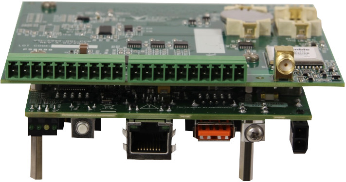
A custom RIO Mezzanine card was designed and built for the National Instruments Single-Board RIO platform to provide access to simultaneously-sampled signals from the 3-phase and neutral lines of an AC power source. Timing synchronization between physically-separated installations was provided by monitoring GPS timing signals. Custom VIs were developed to retrieve the sampled data points and GPS timing for subsequent processing and analysis.
Solution
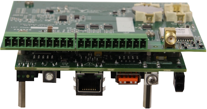
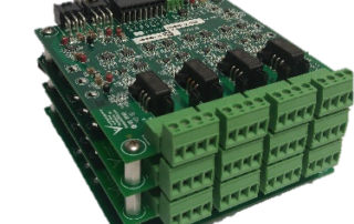
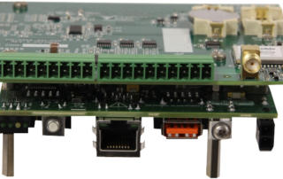
Figure 1 – Power Line Data Acquisition sbRIO RMC Module with GPS Timing
We needed 8 channels of simultaneously-sampled analog inputs (AI), each capable of sampling at least 50 kHz. These AI channels sample the voltage and current of the neutral and three phase power lines. Furthermore, to coordinate power and load fluctuations across many measurement locations, a world-wide synchronization signal is needed.
The Single-Board RIO (sbRIO) platform from National Instruments offers an excellent balance between off-the-shelf capability and custom design needs in a reasonably small package. The sbRIO provides the processor, memory, and connectivity while the RIO Mezzanine Card (RMC) provides the I/O and signal conditioning needs. See our white paper, Developing Embedded Systems: Comparing Off-the-Shelf to Custom Designs, for a discussion of the benefits of using this approach.
We designed the RMC for the simultaneously-sampled analog inputs and a GPS receiver. The RMC was mounted to a sbRIO-9606. Some design specifications were:
- 8 analog input channels: simultaneous sampling at 50 kHz, ±10 V range, 16-bit resolution
- GPS receiver with Pulse Per Second (PPS) timing signal with 60 ns accuracy
- SMA Connector for external GPS active antenna
- 20 position terminal block for analog inputs and shields, removable for wiring
- Operates inside an enclosure with internal conditions -40 to 55 °C temperature
An image of the designed RMC and the sbRIO-9606 is shown below. Since the A/Ds reside on the RMC, the data bytes are accessed by sbRIO FPGA VIs code communicating through an SPI data bus designed into the RMC. The internal real time clock coupled with the GPS PPS signal allowed for timing accuracy within a GPS region well under +/- 1 uS of accuracy for all data sampled no matter the location, internally or from unit to unit within feet or 1000s of miles away.
Conclusion
The combination of the sbRIO off-the-shelf platform and the custom RIO mezzanine card (RMC) for I/O makes a powerful, cost-effective, and yet configurable solution for measurements of AC power signals. With the GPS component on the RMC, measurement units can be placed at dispersed locations while still providing adequate synchronization of acquired waveforms for localizing and understanding disturbances in power transmission and distribution, irrespective of any specific application. If you have an embedded monitoring application that you’d like help with, you can reach out to chat here. If you’d like to learn more about our circuit board design capabilities, go here.
Online Monitoring of Industrial Equipment using NI CompactRIO
Online Monitoring of Industrial Equipment using NI CompactRIO
Improving Maintenance of expensive industrial equipment
Client – Large Industrial Equipment Manufacturer
Challenge
The maintenance of the equipment was not always done at the prescribed intervals because the cost of shutting down the plant is significant. This sometimes resulted in an equipment failure. This particular application is for equipment/machinery in the energy/power industry (a generator).
Solution
The online monitoring system monitors a particular parameter of interest to send warnings and alarms to the control room so that the operators know when maintenance needs to be performed on the particular part of interest. This system has been installed in multiple plants.
Benefits
- Enables condition-influenced maintenance intervals vs periodic intervals
- Reduces probability of catastrophic failure by providing warning indicator
System Overview
The system monitors the generator collector health. NI-based data acquisition hardware acquires the signal of interest, logs the raw data, processes the parameter of interest, and triggers/sends warnings and alarms to the control room. LabVIEW FPGA was used for analog and digital IO and a sensor check. LabVIEW Real Time was used for the calculation, data logging, serving data to the HMI and alarm/warning checking.
| SOFTWARE FUNCTIONS |
|---|
| Touchscreen GUI for data/alarm display and system configuration |
| Data logging |
| Signal processing and alarming |
| HARDWARE USED (selected by customer) |
|---|
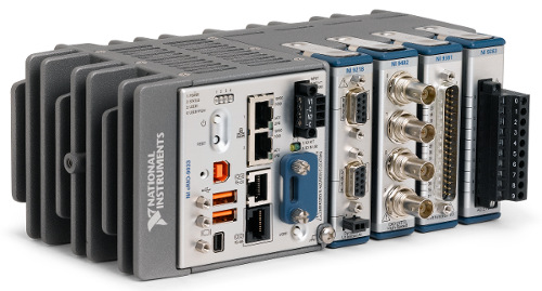
| NI cRIO |
| NI Touch Panel Computer |
| Multiple NI C Series Modules |
| INTERFACES / PROTOCOLS |
|---|
| TCP/IP |
*- images are representative, not actual
Industrial Equipment Remote Online Condition Monitoring

Industrial Equipment Remote Online Condition Monitoring
Using NI CompactRIO
Client
A manufacturer of large industrial mission-critical equipment in the electrical energy / power industry.
Challenge
Our client had three main goals in mind. They wanted to:
- Decrease unanticipated downtime and maintenance expenses
- Provide a more complete picture of machine operation and state
- Improve equipment usage tracking.
Solution
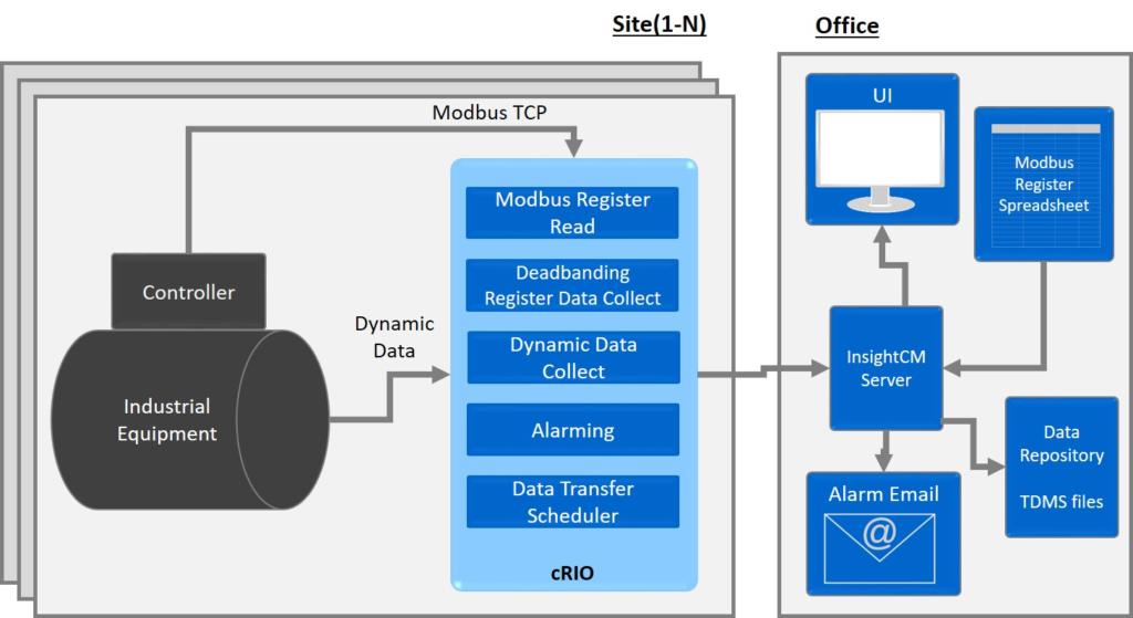
The solution is a multi-node (i.e. multi-site) remote monitoring system that utilizes an NI cRIO-based controller with customized NI InsightCM monitoring software.
Benefits
- Monitors vibration signals to predict expensive equipment failures
- Monitors current machine state via Modbus from other equipment in the system, including the primary system controller
- Provides alerts via email when any designated parameter is out of range
System Overview
The remote monitoring system monitors equipment condition by taking several vibration signal measurements along with reading over 500 Modbus registers. Local InsightCM vibration analysis on the cRIO extracts key features from the accelerometer data. Limit detection is run on these features and other equipment state and alarms are triggered when data is out of bounds. Information collected at multiple sites is sent to a central location either at periodic intervals or based on an alarm condition.
| SOFTWARE |
|---|
| NI InsightCM software |
| Modbus register configuration & reading |
| Dead banding-style register data collection to decrease amount of data captured and transferred |
| Dynamic signal data capture |
| Alarming detection |
| Data transfer scheduling |
| Semi-real-time alarm channel display |
| HARDWARE USED |
|---|
| NI cRIO |
| NI IEPE Analog Input Module |
| Microsoft Windows Server to host the NI InsightCM server software |
| INTERFACES / PROTOCOLS |
|---|
| Modbus TCP |
| Ethernet TCP/IP |
Industrial Embedded Control for Advanced Manufacturing
Industrial Embedded Control for Advanced Manufacturing
Energy & Aerospace components manufacturing
Client – Automated Dynamics
Challenge
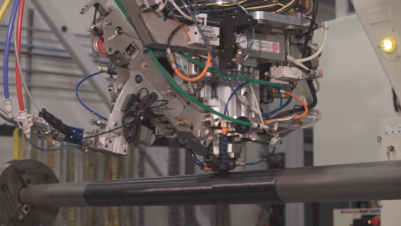
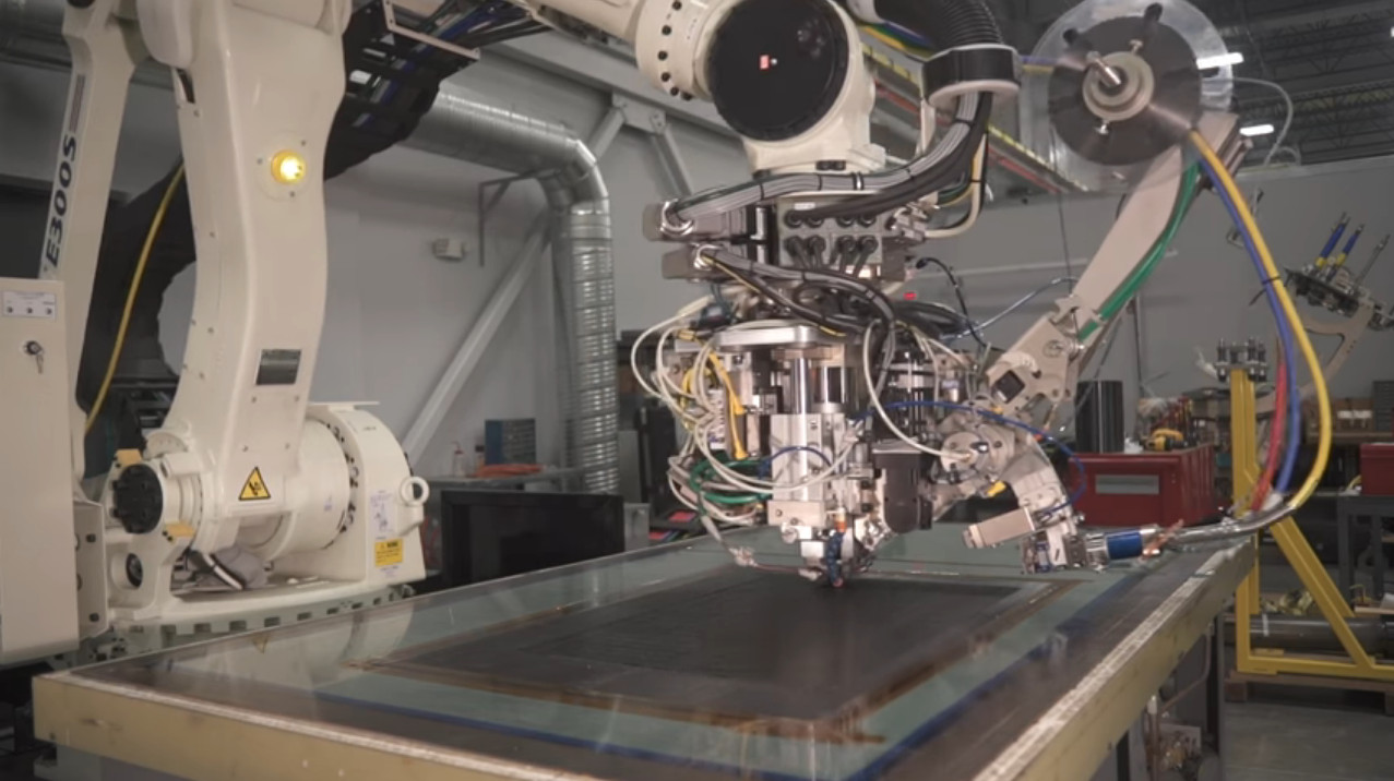
Utilize laser energy to heat thermoplastic or thermoset composite during an automated fiber placement manufacturing process.
Solution
Starting from a proof of concept developed by Automated Dynamics, Viewpoint developed the industrial embedded laser controller software for the automated fiber placement manufacturing equipment. The hardware utilized was an off-the-shelf CompactRIO controller from National Instruments.
Benefits
- High-speed temperature control
System Overview
See it in action here:
Industrial Embedded – Industrial Equipment Control

Industrial Embedded – Equipment Control – VAR Compensator
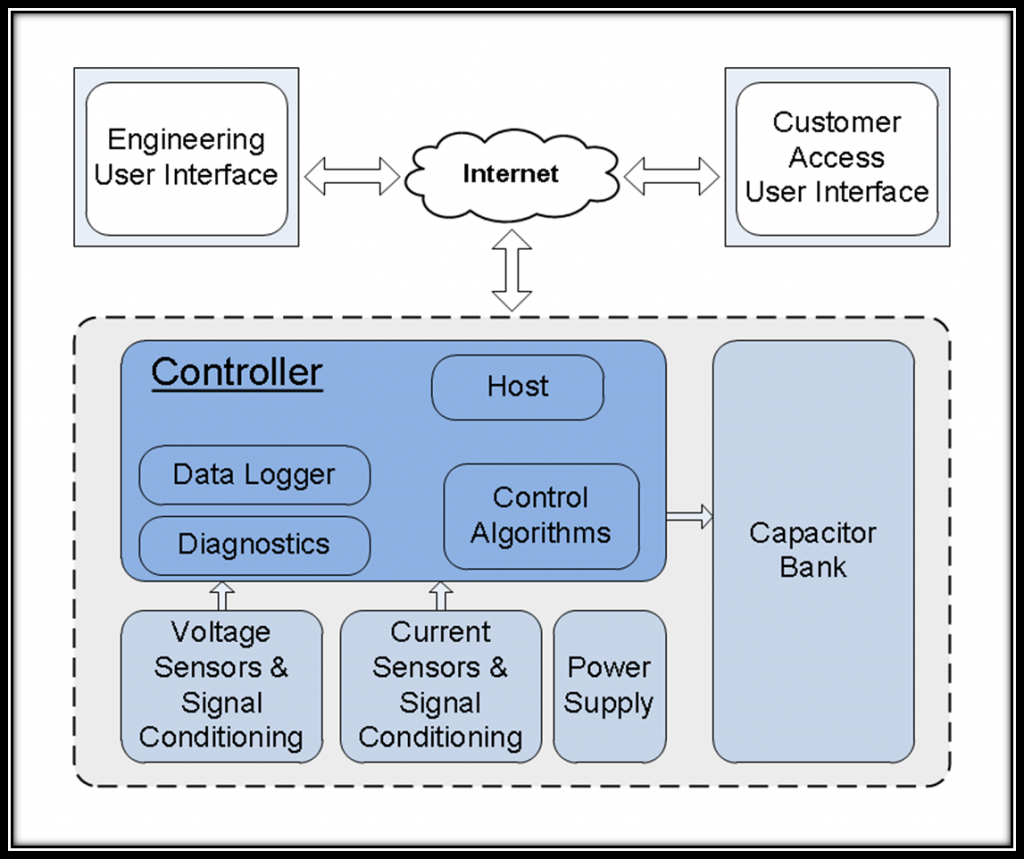
Keeping the Electrical Grid Healthy with VAR Compensation
Modular Embedded System Shortens Development Time and Reduces Risk in Static VAR Compensation System
Client: T-Star Engineering & Technical Services: A manufacturer of electrical power delivery equipment.
Background
The U.S. power grid is a large electrical circuit that, although has some amount of isolation between loads, is certainly interconnected at drop points, which is what customers care about most.
SVCs are generally worth considering in scenarios where large electric motors are being utilized (e.g. mills, recycling plants, mines). Problems such as voltage sag, voltage flicker, and current harmonics can cause reduced motor torque, lights to flicker, and equipment damage.
Challenge
T-Star has significant domain expertise in stabilizing medium voltage power systems. Viewpoint has significant domain expertise in the realm of measurement and control systems. The team at T-Star needed a well-supported intelligent device for their new generation Static VAR Compensator (SVC). They wanted a highly reliable solution that had minimized the time-to-market and a highly predictable future migration path for higher volume production. They also needed multi-channel precision timing, and high speed logging in a device certified for operation in dirty industrial environments.
Solution
Viewpoint was asked to develop the controller for T-Star’s Static VAR Compensator (SVC) using a carefully constructed specification. The chosen controller platform is a National Instruments (NI) Compact RIO due to its modular feature set, networking capabilities, and associated supportability and quality that comes with an industrial-grade off-the-shelf controller. T-Star and Viewpoint have made very complementary GSD (Get Stuff Done) teammates.
As the grid gains intelligence, this class of smart/dynamic power quality system will likely become more critical.

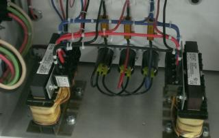
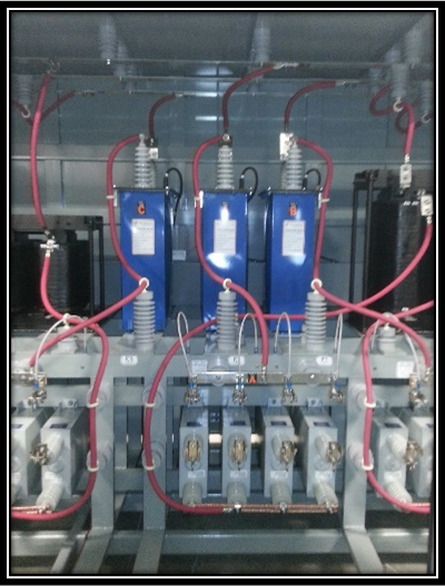
Cabinets for an SVC located at a remote mine in British Columbia
Inside an SVC
Benefits
- The platform supports other future configurations that are outside the phase one scope of this project.
- Time-to-market is critical for T-Star. The initial proof of concept was completed in weeks.
- The Linux-based OS, well known in the embedded community, provides a rich ecosystem for enhanced usability (e.g. network stack), and real-time operation.
- Secure access through VPN with built-in firewall and user account control and permissions allows for remote diagnosis, health monitoring, and gathering of online information.
- An FPGA allows for deterministic timing and parallel processing.
- With COTS hardware, future upgrades are simplified with code base reuse and recompiling for new hardware.
- The NI platform provides a migration path to a lower-cost solution once hardware configurations are locked down and production volumes increase above a certain level.
- The NI control hardware is certified (certifications in the domains of CE, FCC, UL, etc.) for marine applications and other challenging environments.
System Overview
The SVC tunes a highly inductive load by dynamically injecting a variable amount of capacitance due to the measured load. Voltage and current sensors feed a series of control algorithms which determine the voltage and current imbalance in order to inject the appropriate amount of capacitance into the power system. This algorithm acts on a cycle-by-cycle basis. The figure below illustrates the system makeup.

Industrial Automation – Improving Manufacturing Process with a semi-automated welder
Industrial Automation – Improving Manufacturing Process with a semi-automated welder
Automating a battery welder to improve consistency and increase throughput
Client
Industrial manufacturer of battery stacks

Challenge
The previous welding method was all manual, prone to errors and inconsistency. The old system also required the operator be in contact with the module while welding without any safety shielding.
Solution
The welder semi-automates the ultrasonic welding of terminals on a battery module as part of the manufacturing process. It allows for welds to be conducted in the same place for every module, reducing variability and operator errors. This system is also quicker than doing the welds manually.
Benefits
- Increased weld consistency
- Improved operator safety
- Increased welder throughput
System Overview
The system semi-automates the ultrasonic welding of terminals on a battery module. The system consists of an ultrasonic welder, XYZ table, and safety interlocks. The table moves the battery module to the correct welding position. Once in position, the Z portion of the table lowers the welder to the correct welding height. The application sends the signal to the welder to conduct the weld. Weld data is saved to a file from the welder Ethernet interface for later analysis. Viewpoint provided the software for this system, while the client provided the hardware for us to interface with.
Considerable attention was paid to addressing faults in the production process to avoid damage to the operator and the battery module during the welding process, due to the high current output available from the battery module.
| SOFTWARE FUNCTIONS |
|---|
| Welding routing configuration |
| Operator GUI |
| Maintenance mode |
| Interface to welder |
| Interface to table & controller |
| Interface to E-Stop & interlocks |
| INTERFACES / PROTOCOLS |
|---|
| RS-485 |
| Ethernet |
| 24V Digital IO |
Condition Monitoring for Electric Power Generation
Condition Monitoring for Electric Power Generation

Monitoring generator and turbine components of power generation equipment
The CompactRIO-based system has allowed for continuous monitoring, rather than just a periodic review of turbine and generator performance. In addition, by combining the FPGA and the RT processor in a physically small device, the solution has been able to ensure very fast data acquisition, data reduction, and sophisticated analysis.
Client: A multi-national power generation equipment manufacturer
Background
Continuous monitoring of power generation equipment can have a great impact on maintaining a reliable flow of power to consumers as well as alerting the power generation equipment operator to potential equipment damage if timely repairs are not made.
This case study will focus on two measurement systems utilized by a multi-national power generation equipment manufacturer to monitor the generator and turbine components of their power generation equipment.
The manufacturer’s systems needed relatively high-speed waveform sampling, well-suited to the National Instruments CompactRIO platform. Viewpoint Systems provided technical assistance in the development of these systems.
Challenges
The difference in the types of analyses and data rates of the measurement systems required a flexible yet capable hardware platform. Each system needed to work on a generator outputting 50 Hz AC or 60 Hz AC.
Viewpoint’s Solution
The CompactRIO platform and LabVIEW proved to be an excellent solution for the electric power generation condition monitoring system’s data acquisition and analysis needs. The small size and robustness of CompactRIO allowed the system to be placed at a preferred location. In both the flux probe and the blade tip timing, the CompactRIO FPGA could acquire and pre-process the data. The CompactRIO successfully managed – and continues to manage – all analysis, data archiving, and communication with a host PC.
In the case of the tip timing, the data rates were high enough that the detection of the tip location for each signal needed to be performed in the FPGA so that the real-time (RT) layer received a much-reduced data rate of tip locations. The RT processor was able to perform higher level analyses on these timings. Occasionally, a snapshot of a raw tip timing waveform could be passed to the RT processor for archiving and presentation to an engineer. However, due to the data bandwidth and processor loading of the CompactRIO, such snapshots must be infrequent.
For both systems, a master PC managed the operator user interface, long-term data collating, reporting, and archiving of files and statistics. Each CompactRIO connected to this master PC via a TCP/IP connection.
Results
The CompactRIO-based system has allowed for continuous monitoring, rather than just a periodic review of turbine and generator performance. In addition, by combining the FPGA and the RT processor in a physically small device, the solution has been able to ensure very fast data acquisition, data reduction, and sophisticated analysis. By deploying CompactRIO devices, the multi-national power generation equipment manufacturer achieved a cost-effective method of monitoring the power generation facility equipment, ensuring detection of operational issues quickly and easily.
Technical Highlights
Both measurement systems described required sampling rates greater than 10 kHz, restricting the use of traditional PLC-based data acquisition devices and requiring a programmable automation controller (PAC). Each system measured the performance by connecting to special sensors and associated signal conditioning, provided by our customer, such that the data acquisition equipment only needed to support ±10 V signals. Furthermore, each of these systems needed to push data to a master PC for data trending, result archiving, and operator display.
Despite the significant differences in the measurement types, Viewpoint Systems was able to utilize a common set of data acquisition, processing, and connectivity tools, based on the NI CompactRIO platform and LabVIEW, to monitor the system.
More information about each measurement system follows.
Flux Probe
The flux probe system looks for shorts in the windings of the generator. Each time a winding passes under the flux probe, the probe output increases. When a winding is shorted, the field created by the winding is reduced and detected as a lower amplitude output by the flux probe. The position of a shorted winding inside the generator can be located by measuring a key-phasor signal that pulses once per revolution and converting the timing offset of this weakened signal into an angular position. Both flux and key-phasor signals are measured at about 50 kS/s.
Figure 1 shows an example signal output by a flux probe. The local peaks are indicative of winding current. Automated analysis of the amplitudes of the flux signals can be challenging due to changing waveform shape as a function of generator load and severity of shorts.
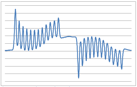
Figure 1 – Example flux signal over a single rotation
A good reference of the flux probe technique is described in the Iris Power Engineering article, “Continuous Automated Flux Monitoring for Turbine Generator Rotor Condition Assessment.”
Turbine Tip Timing
The turbine tip timing system looks for displacement of each turbine blade tip from nominal position. At slow rotational speeds, the spacing between each tip closely follows the uniform blade spacing. At higher speeds, vibrations and resonances can make the blade tips wobble slightly, causing small deviations in the timing of the tip passing by a sensor.
A special proximity sensor detects the tip of the turbine blade, and can be based on optical, eddy-current, microwave, and other techniques. Any positional deviations of a tip from nominal give indications about the mechanical forces on the blade as well as compliance of the blade to those forces as the blade ages. Specifically, each blade has natural resonances and compliance, both of which can change if the blade cracks.
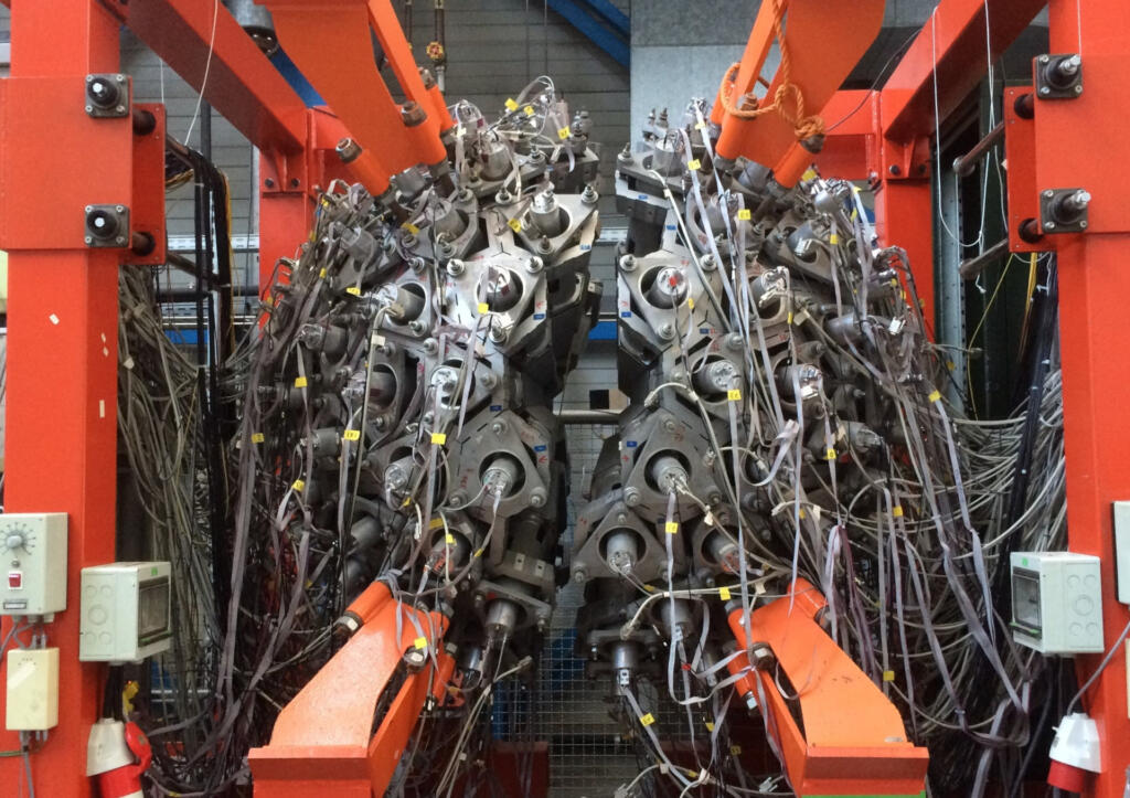
A turbine typically contains several stages and each stage contains many blades. See Figure 2 below for an example. The number of tip sensors per stage is variable; if blade twist is measured, at least two sensors are oriented perpendicular to the rotation direction. Also, the acquisition rate from each sensor is fast. For example, consider a stage with 60 blades, the width of each blade occupying about 1/10 the space between adjacent blades, and a generator running at 3600 RPM (60 Hz). The tip sensor would detect a pulse every 1/3600 s, lasting for less than about 1/36000 s, as the blades passed by. Accurate location of the pulse peak or zero-crossing then requires sample rates over 100 kS/s. Because multiple sensors are typically used, tip timing measurement systems can easily generate 10s of MBs of data per second.
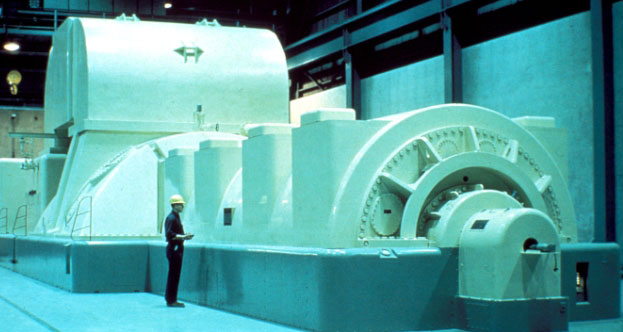
Figure 2 – Example generator turbine blades
A good reference for the tip timing technique is described in the article by ITWL Air Force Institute of Technology – Poland, “Application of Blade-Tip Sensors to Blade-Vibration Monitoring in Gas Turbines.”
We specialize in using FPGAs for the control algorithms involved in power conversion and motor control. FPGAs offer advantages over traditional DSPs because of the inherent parallelism of code execution. In addition, we prefer to program the FPGAs using LabVIEW which, based on the support for a broad range of FPGA targets, allows us to use different target platforms for prototyping (e.g., cRIO) and deployment (e.g., sbRIO) with no or minimal FPGA code changes.
Algorithms are based around Space Vector Modulation (SVM) for PWM control of the switches. Additional control needs are handled with extra FPGA-based algorithms and/or by using a real-time OS (RTOS).
Signals in and out of the FPGA are conditioned via custom and COTS signal conditioning depending on the application power needs. We typically start algorithm development and testing on a test bench at low power levels, enough to drive small motors (e.g., AC and DC) and generators (e.g., DFIG) that can be controlled and monitored with ±10 V signals. After algorithms are vetted, the higher power equipment is connected to the controller.
AC signals generated from separated power sources and used to drive motors can be synchronized via various techniques including Time Sensitive Networking (TSN) technology.
We’ve helped teams at some of the world’s most innovative companies